68 UMG70XV3-4EN 12.01.2009
7 Installation of FLUXUS G709
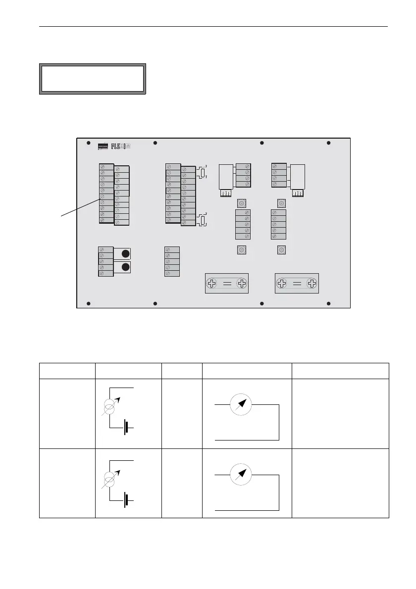
7.5 Connection of the Outputs
• Connect the leads to the terminals of terminal strip KL1 as displayed (see Fig. 7.8 and Ta-
ble 7.9).
Fig. 7.8: Connection of the outputs
• Close the flowmeter. Screw the cover on the housing.
Configure the outputs (see chapter 18). The terminals
to be used for the connection of the output are dis-
played at the end of the configuration dialog (here: P1+
and P1- for the active current loop).
Table 7.9: Circuits of the outputs
output FLUXUS terminal circuits
active
current loop
Px+
(red)
(black)
Px-
R
LOAD
< 500
semi-active
current loop,
operated as
active current
loop
Px+
(red)
(black)
Px-
R
LOAD
< 50
I1 active loop
Terminal:P1+,P1-
T 1 A
T 1 B
P T 1 0 0
T 4 B
T 4 A
P T 1 0 0
B :A :
S A 3
S A 1
S A 2
S A 4
S B 3
S B 1
S B 2
S B 4
A V S
A V
A R S
A G N
A R
B V S
B V
B R S
B G N
B R
A C
2 3 0 V
1 0 0 . . .
D C
V O L T
L O W
4 A +
4 B -
4 2
4 3
4 1
L +
L -
N
L 1
P E
P 4 +
P 5 +
P 2 +
P 3 +
P 1 +
P 6 a
P 7 a
P 7 +
P 5 a
P 6 +
P 4 -
P 5 -
P 2 -
P 3 -
P 1 -
P 6 b
P 7 b
P 7 -
P 5 b
P 6 -
T 2 A
T 2 B
T 1 B
S 1
T 1 A
T 4 A
T 4 B
T 3 B
S 3
T 3 A
T 2 a
T 2 b
T 1 b
S 2
T 1 a
T 4 a
T 4 b
T 3 b
S 4
T 3 a
KL1 KL3 KL5 KL7
KL2 KL4
KL6 KL8
outputs
(KL1)