162 UMG70XV3-4EN 12.01.2009
18 Outputs
18.6 Behavior of the Alarm Outputs
18.6.1 Apparent Switching Delay
Measured values and totalizer values will be displayed rounded to two decimal places.
The limits, however, will be compared to the non-rounded measured values. This might
cause an apparent switching delay when the measured value changes marginally (less
than two decimal places). In this case, the switching accuracy of the output is greater
than the accuracy of the display.
18.6.2 Reset and Initialization of the Alarms
After a cold start, all alarm outputs will be initialized as follows:
Press three times key C during measurement to set all alarm outputs to the idle state.
Alarm outputs whose switching condition is still met will be activated again after 1 s. This
function is used to reset alarm outputs of type HOLD if the switching conditions is not met
anymore.
By pressing key BRK, the measurement will be stopped and the main menu selected. All
alarm outputs will be de-energized, independently of the programmed idle state.
18.6.3 Alarm Outputs during Transducer Positioning
When the positioning of the transducers begins (bar graph display), all alarm outputs
switch back to the programmed idle state.
If the bar graph is selected during measurement, all alarm outputs switch back to the pro-
grammed idle state.
An alarm output of type HOLD being activated during the previous measurement remains
in the idle state after transducer positioning if the switching condition is not met anymore.
Switching of the alarms into the idle state will not displayed.
18.6.4 Alarm Outputs during Measurement
An alarm output with switching condition MAX or MIN will be updated max. once per sec-
ond to avoid humming (i.e. fluctuation of the measured values around the value of the
switching condition).
An alarm output of type NON-HOLD will be activated if the switching condition is met. It
will be deactivated if the switching condition is not met anymore. The alarm remains acti-
vated min. 1 s even if the switching condition is met shorter.
Alarm outputs with switching condition QUANTITY will be activated when the limit is
reached.
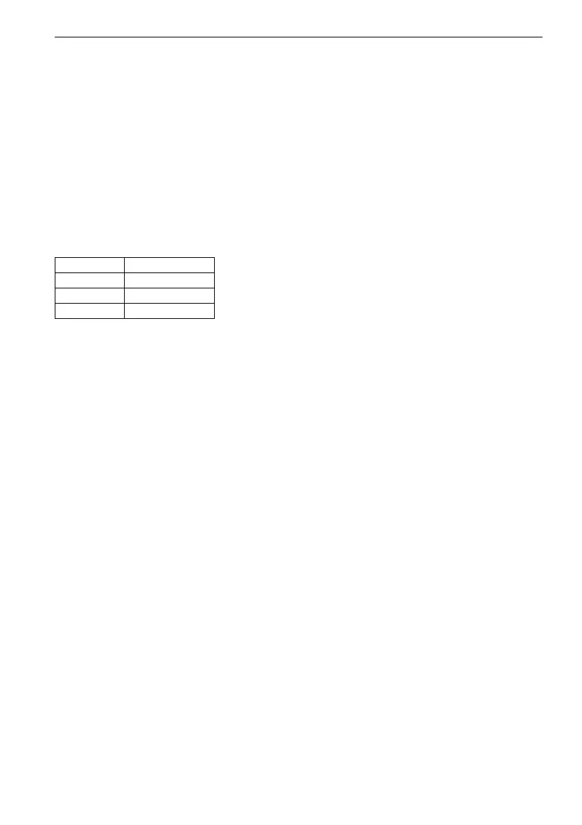
Table 18.7: Alarm state after initialization
FUNC OFF
TYPE NON-HOLD
MODE NO CONT.
LIMIT 0.00