66 UMG70XV3-4EN 12.01.2009
7 Installation of FLUXUS G709
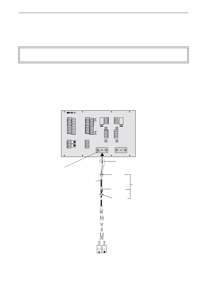
7.3 Connection of the Transducers - Connection System AS
• Open the cable gland of the extension cable (see Fig. 7.6).
• Push the basic part of the cable gland towards the AMP-Quick and SMB connectors,
the cap nut and the compression part in the other direction.
• Push the extension cable through the shield terminal to terminal strip KL6 for measur-
ing channel A and to terminal strip KL8 for measuring channel B (see Fig. 7.6).
• Pull the extension cable back until the brushed back outer shield is below the shield
terminal (see Fig. 7.6).
• Fix the extension cable and the outer shield to the shield terminal.
• Connect the AMP-Quick and the SMB connectors with the sockets of the flowmeter (see
Fig. 7.6 and Table 7.7).
Fig. 7.6: Transducers (ATEX zone 2, FM Div. 2, without explosion protection)
- direct connection
Note! Cap nut, compression part and basic part of the cable gland remain on
the cable.
T 1 A
T 1 B
P T 1 0 0
T 4 B
T 4 A
P T 1 0 0
B :A :
S A 3
S A 1
S A 2
S A 4
S B 3
S B 1
S B 2
S B 4
A V S
A V
A R S
A G N
A R
B V S
B V
B R S
B G N
B R
A C
2 3 0 V
1 0 0 . ..
D C
V O L T
L O W
4 A +
4 B -
4 2
4 3
4 1
L +
L -
N
L 1
P E
P 4 +
P 5 +
P 2 +
P 3 +
P 1 +
P 6 a
P 7 a
P 7 +
P 5 a
P 6 +
P 4 -
P 5 -
P 2 -
P 3 -
P 1 -
P 6 b
P 7 b
P 7 -
P 5 b
P 6 -
T 2 A
T 2 B
T 1 B
S 1
T 1 A
T 4 A
T 4 B
T 3 B
S 3
T 3 A
T 2 a
T 2 b
T 1 b
S 2
T 1 a
T 4 a
T 4 b
T 3 b
S 4
T 3 a
AMP-Quick and
SMB connectors
shield terminal
transducers:
•ATEX zone 2
•FM Div. 2
• without explosion protection
basic
part
compres-
sion part
cap nut
cable gland
outer shield
KL6 KL8