42 UMG70XV3-4EN 12.01.2009
6 Installation of FLUXUS G704
6.4.2 Transducers (ATEX Zone 1) - Connection via Junction Box
Connection of the Extension Cable with the Flowmeter
• Remove the left blind plug for the connection of the transducers (see Fig. 6.4 ).
• Open the cable gland of the extension cable. The compression part remains in the cap
nut.
• Push the extension cable through the cap nut and the compression part.
• Prepare the extension cable with the cable gland. Cut the outer shield and brush it
back.
• Tighten the gasket ring side of the basic part in the housing.
• Insert the extension cable in the housing.
• Fix the cable gland by screwing the cap nut on the basic part.
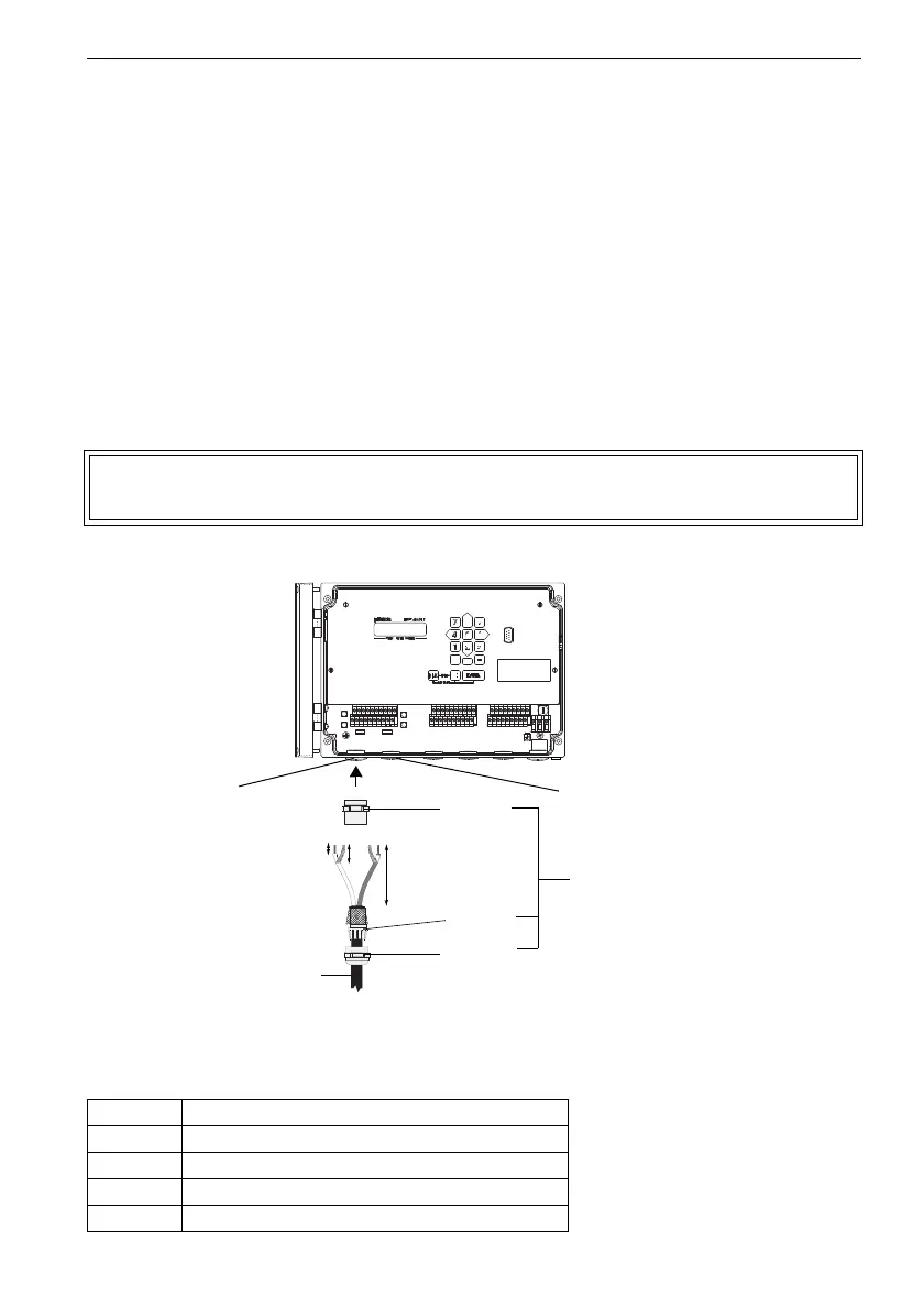
• Connect the leads to the terminals of the flowmeter (see Fig. 6.4 and Table 6.2).
Fig. 6.4: Transducers (ATEX zone 1) - connection via junction box,
connection of the extension cable to the flowmeter
Attention! For good high frequency shielding it is important to assure good con-
tact between the cable shield and the cap nut (and thus the housing).
Table 6.2: Terminal assignment
terminal connection
AV white or marked cable (core)
AVS white or marked cable (inner shield)
ARS brown cable (inner shield)
AR brown cable (core)
70 mm
20 mm
10 mm
basic
part
compres-
sion part
cap nut
extension cable
cable gland
transducers
measuring channel A
transducers
measuring channel B