36 UMG70XV3-4EN 12.01.2009
5 Selection of the Measuring Point
5.4 Selection of the Measuring Point Taking into Account Flow
Profile and Influence of Noise
• Select a measuring point area where the flow profile is fully developed (see section
5.2).
• Select the measuring point within this area so that the influence of noise can be ne-
glected (see 5.3).
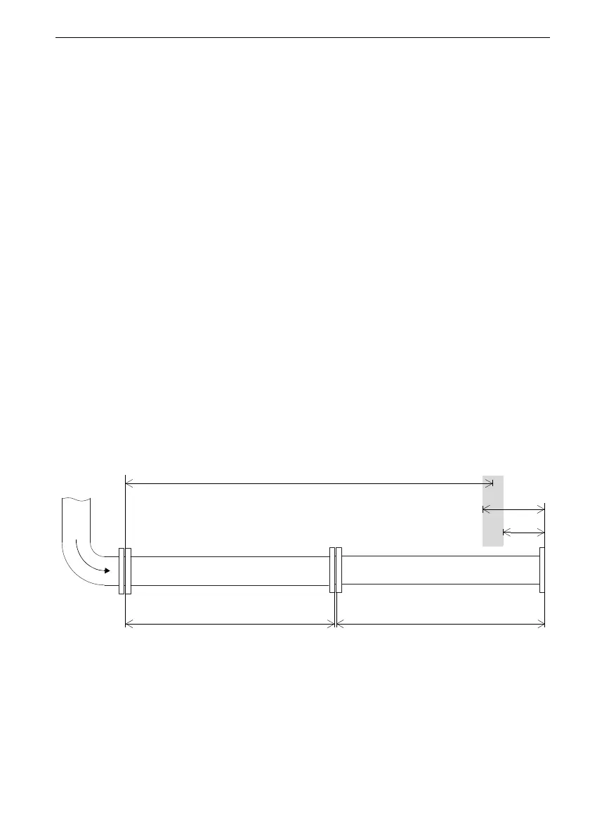
Considering flow profile and influence of noise, the measuring point can be selected in
the area 3...(7.5 - 2) D on the right side of pipe segment 2 (with max. distance from the el-
bow). In the example, a distance of 36 D from the elbow was selected.
example: medium: natural gas
pipe material: stainless steel
length of pipe segment 1: 20 D
length of pipe segment 2: 20 D
number of sound paths: 2
• measuring point area with developed flow profile:
disturbance source: 90° elbow
recommended measuring point area: l 20 D (complete pipe segment 2) (see Table
5.1)
• measuring point area with low influence of noise:
reflection point: flange
recommended measuring point area: l 3 D and outside of l = (7.5 ± 2) D on pipe
segment 2 (see Table 5.1)
Fig. 5.3: Measuring point area with developed flow profile and low influence of noise