UMG70XV3-4EN 12.01.2009 47
6 Installation of FLUXUS G704
6.4.4 Transducers (ATEX Zone 2, FM Div. 2, without Explosion
Protection) - Connection via Junction Box
Connection of the Extension Cable with the Flowmeter
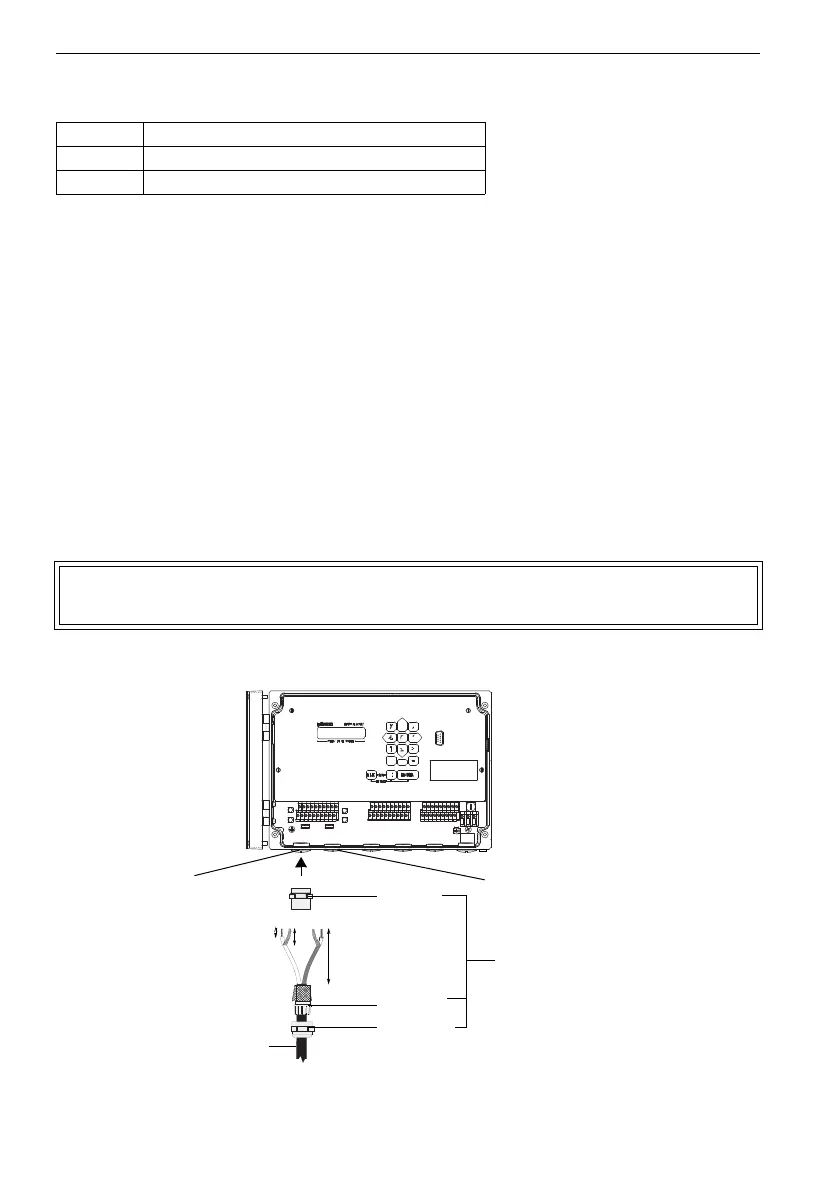
• Remove the left blind plug for the connection of the transducers (see Fig. 6.8).
• Open the cable gland of the extension cable. The compression part remains in the cap
nut.
• Push the extension cable through the cap nut and the compression part.
• Prepare the extension cable with the cable gland. Cut the outer shield and brush it
back.
• Tighten the gasket ring side of the basic part in the housing.
• Insert the extension cable in the housing.
• Fix the cable gland by screwing the cap nut on the basic part.
• Connect the leads to the terminals of the flowmeter (see Fig. 6.8 and Table 6.6).
Fig. 6.8: Transducers (ATEX zone 2, FM Div. 2, without explosion protection) -
connection via junction box, connection with the flowmeter
Table 6.5: Terminal assignment
terminal connection
X_AV SMB connector (brown cable, marked white)
X_AR SMB connector (brown cable, marked black)
Attention! For good high frequency shielding it is important to assure good con-
tact between the cable shield and the cap nut (and thus the housing).
70 mm
20 mm
10 mm
basic
part
compres-
sion part
cap nut
extension cable
cable gland
transducers
measuring
channel A
transducers
measuring
channel B