7
3 Installation
The unit is designed for indoor installation.
3.1 Inspection/Maintenance
The unit must be installed with space for service and
maintenance such as filter replacement and cleaning
the fans and exchanger. It is also important for the unit
to be located so that the electrical cabinet is easily ac-
cessible for electrical connection, troubleshooting and
future component replacement.
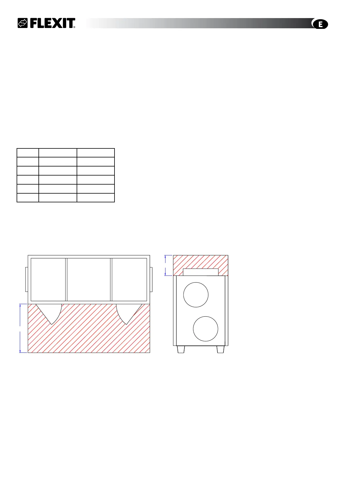
3.2 Space Required
Type A B
L12 550 mm 400 mm
L18 1000 mm 500 mm
L20 1000 mm 500 mm
L30 1000 mm 500 mm
L50 1400 mm 100 mm
See the separate dimensioned drawing for connection
of the water battery (pipe location), Chap. 2.3.
These are minimum requirements that only take service
needs into account. If other statutory requirements re-
quire a greater distance, they must be complied with, for
example for electrical safety.
3.3 Technical Room Requirements
The unit must be placed in a separate technical room
with a gully. Ceiling/floor/walls/doors must be in the
necessary fire class.
3.4 Recommended Sound Absorption and
Sound Transfer
The main silencers must be placed near the unit, prefer-
ably in the technical room.
The unit should be placed by a wall that has no room on
the other side that is sensitive to noise. The unit should
not be less than 400 mm from the wall. If the unit is
placed against a wall, low-frequency sound may create
vibrations in the wall.
Sound may also be transferred through the floor if the
mass and rigidity of the floor are not sufficient.
Technical rooms should be fitted with floating concrete
floors to prevent sound transfer on account of vibration.
When installing the unit, fabric bosses must be fitted be-
tween the unit and the duct system. It is also important
for the unit not to bear the weight of the ducts.
Busbars or water pipes must not prevent the unit from
moving freely on the vibration dampers.
3.5 Air Intake/Exhaust
The distance between the air intake and air exhaust must
be so great that air circulation is prevented.
The fresh air intake must be placed away from traf-
fic/smoke/dust/walls exposed to the sun. The air intake
should be placed min. 1 m above ground level to reduce
the risk of clogging with snow and leaves. When design-
ing the intake/exhaust chambers, it is necessary to take
drainage into account.
Follow the suppliers’ recommendations for max./min. air
flow rates through the intake/exhaust gratings/roof hats.
3.6 Stop Damper in Air Intake/Exhaust
(Accessory)
Used to prevent self-ventilation when the unit is
stopped.
Must always be used in systems with water batteries as
protection against frost.
B
A
Fig. 8