Page 5
Pin No. Function
1 Microphone Element Pilot
2 Microphone ground
3 Microphone Element Co Pilot
4 Music audio input(Monoral)
5 Intercom (ground to activate)
6 PTT Co Pilot
7 PTT Pilot
8 LED backlight (ground to activate/brightness adjustment by the variable resistor)
9 Positive 12V/24V DC
10 Positive 12V/24V DC
11 Negative ground
12 Negative ground
13 Memory change(toggle ground)
14 Headpohne output
15 Speaker output
5 BEFORE BEGINNING INSTALLATION
Again check through the supplied parts list.
5.1 Installation parts identification
All connectors are supplied for installation of this transceiver. Parts include a J001 socket and
backshell. Certified aircraft must use approved materials.
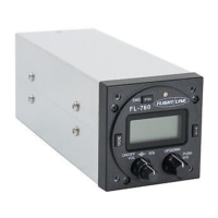
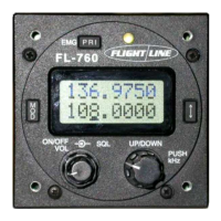
5.2 Transceiver installation and removal
The following section describes the proper installation and removal of the FL-760A transceiver.
5.3 General
The following information is provided as a guide for installation in uncertified aircraft. If the
FL-760A is to be installed in a certificated aircraft, the installation must be done by a certified
repair station.
5.4 Pin connections
(MIC1)
(MIC2)
Note: If you intend using a dynamic mike (non amplified) you must provide amplification. A
simple 2 transistor amplifier with gain control will do.
The backlight can be adjusted and dimmed. (Refer to user setting of page10).
5.5 Mechanical installation
● Carefully measure the proposed mounting site for clearance. Allow for rear cabling and
connectors. Use the template supplied to carefully drill a 58mm hole.
● Drill the mounting holes (4mm)
● The mounting holes support the weight of the transceiver and should not be oversized.
● Run all wires that will be required for your particular installation.
Following are the recommended configurations for use in Gliders and Ultralights: