6
© Copyright 2016. All rights reserved.
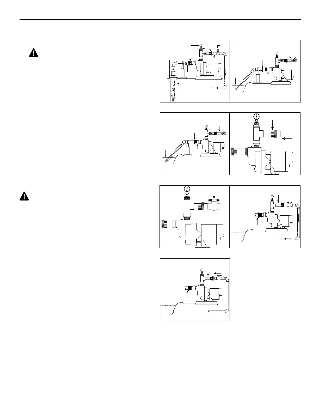
PUMP INSTALLATION FOR WELL AND SURFACE WATER
1. Mount pump on a solid foundation as close to
the water source as possible.
CAUTION: Support the 2 in. inlet
pipe from the well or lake to the inlet port
to prevent sagging. Sagging will create air
pockets within the pipe that will prevent the
pump from priming and operating correctly.
2. Glue female 2 in. union to the end of inlet
pipe leading from the water source.
3. Connect the 2 in. union together to complete
the inlet line to the pump.
4. Glue a 6 in. piece of 1-1/2 in. pipe to the
female portion of the 1-1/2 in. union.
5. Glue 1-1/2 in. ball valve to the other end of
the 6 in. piece of pipe.
6. Connect the 1-1/2 in. outlet pipe to the
sprinkler system by gluing in additional
sections of pipe as needed.
7. Connect union to ensure proper t. Do not
tighten until after priming.
CAUTION: Do not glue union together.
Water Level
Discharge to
Sprinkler System
Well Seal
100 PSI
Pressure
Gauge
Union
Ball
Valve
Outlet
Pipe
Inlet
Pipe
Well
Union
Water
Level
Outlet Pipe
Inlet
Pipe
2 in.
Female
Union
Fig 2Fig 1
Water
Level
Outlet Pipe
Inlet
Pipe
2 in.
Union
1-1/2 in.
Union
Fig 4Fig 3
Ball Valve
Outlet Pipe
Inlet
Pipe
Discharge to
Sprinkler System
Fig 6Fig 5
Outlet Pipe
Inlet
Pipe
Discharge to
Sprinkler System
Fig 7
 Loading...