Do you have a question about the Flint & Walling SP10P1 and is the answer not in the manual?
Covers electrical shock hazards, necessary precautions, and warnings for safe operation.
Includes chemical alerts, burn warnings from hot surfaces, and product damage prevention.
Lists essential tools and parts for pump assembly, including pipes, fittings, and tools.
Details optional parts for assembly like priming plugs, unions, and ball valves.
Covers typical setups, location, ventilation, freezing protection, and water supply.
Includes warnings against running dry, maintaining air-tight systems, and proper wire sizing.
Cautions for dry-fitting, proper gluing, and using thread tape/paste during assembly.
Instructions for connecting outlet and inlet piping, adaptors, and priming plug.
Steps for well installations: connecting foot valve, pipe, elbow, and well seal.
Steps for surface water installations: connecting inlet pipe, elbow, and pipe support.
Instructions for mounting the pump and connecting the inlet pipe from the water source.
Steps for connecting the outlet pipe and installing the 1-1/2 in. ball valve.
Emphasizes electrical shock hazards, proper wiring, grounding, and disconnecting power.
Details wire size, circuit requirements, and ensuring power source matches pump needs.
Steps for removing the motor cover, threading the strain relief, and inserting the wire.
Instructions for changing pump wiring to run on 115 volts from factory 230 volts.
Detailed steps for filling the pump cavity with water to ensure proper priming.
Actions to take if the pump fails to prime within five minutes, checking for leaks.
Notes that the pump and motor require no lubrication as bearings are factory greased.
Step-by-step guide for replacing the rotary seal assembly, including cautions.
Addresses causes and corrective actions for little or no discharge, or low pressure.
Covers potential causes like foundation issues or foreign material causing vibration/noise.
Troubleshoots issues like incorrect wiring, blown fuses, or motor overheating.
Identifies causes and solutions for the pump losing its prime, such as air leaks.
Lists available replacement parts with item descriptions, part numbers, and quantities.
Details product specifications including HP, suction lift, discharge pressure, and pipe sizes.
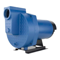
This document describes a Lawn Sprinkler and Irrigation Pump, designed for use in various water sources such as ground water wells, lakes, ponds, or streams. The pump's primary function is to draw water from a source and deliver it to a sprinkler system for irrigation purposes.
The pump operates by creating suction to draw water from a source into its inlet port, then pressurizing and discharging it through the outlet port to the sprinkler system. It is equipped with a dual-voltage motor, capable of running on either 115 volts or 230 volts, offering flexibility in electrical setup. The pump is factory-preset to run at 230 volts, which is generally more economical and requires a smaller wire size.
Key components of the pump system include a foot valve or suction strainer with a check valve at the water source to prevent backflow and maintain prime, and various PVC pipes and fittings to connect the pump to both the water source and the sprinkler system. A priming plug, optionally with a pressure gauge, is used to fill the pump casing with water before initial operation, ensuring the pump is primed and operates correctly. Unions are recommended for easy removal of the pump from the system for maintenance or winterization. A ball valve can be incorporated into the outlet line to prevent backflow from the sprinkler system when the pump is removed.
The pump is designed to handle water from a vertical lift of up to 25 feet from the lowest water level to the pump intake. The horizontal distance from the pump inlet to the water source can affect its operation, with a recommended maximum of 60 feet for optimal performance.
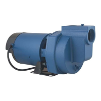
For optimal performance, the pump should be located as close as possible to the water source and protected from the elements. Proper ventilation and drainage are crucial to prevent damage to the motor from heat and moisture. In areas prone to freezing, the pump and all associated piping must be protected; this may involve draining the pump or completely removing it from the sprinkler system during cold weather.
Before initial startup, the pump must be primed by filling its casing with water. This involves disconnecting the outlet union, removing the priming plug, and slowly filling the pump cavity until water comes out of the air relief hole on top of the pump. Once filled, the air relief plug and priming plug are reinstalled, and the outlet union is reconnected. The pump should not be run against a closed discharge, as this can lead to hazardous pressure buildup, risk of explosion, and scalding.
The electrical connection requires careful attention to local electrical and safety codes, as well as the National Electrical Code (NEC) and OSHA regulations. The unit must be securely and adequately grounded. The power cable should be protected from sharp objects, oil, grease, hot surfaces, or chemicals, and any damaged wiring should be replaced immediately. A dedicated circuit breaker is recommended for the pump.
The motor's dual voltage capability allows users to switch between 230V (factory default) and 115V. This involves reconfiguring specific wires on the terminal board using needle-nose pliers, as detailed in the electrical instructions.
The pump and motor are designed for minimal maintenance, with the motor's ball bearings being factory-greased and requiring no further lubrication under normal operating conditions.
A key maintenance task is the replacement of the rotary seal assembly. This procedure requires disconnecting the power supply and carefully handling the precision-lapped faces of the sealing components to avoid damage. The process involves disengaging the pump body from the motor, removing the diffuser and impeller, and then prying out the old ceramic seal and rubber gasket from the mounting bracket. The recess and motor shaft must be thoroughly cleaned before installing the new rotary seal assembly. To facilitate installation, a drop of liquid soap can be applied to the outside diameter of the new rubber gasket. The ceramic seal and rubber gasket are inserted into the recess, followed by the remaining parts of the rotary seal assembly onto the motor shaft, and finally, the spring, impeller, and diffuser are reinstalled before reassembling the pump body to the motor and mounting bracket.
Troubleshooting guidance is provided for common issues such as little or no discharge, failure to deliver water or develop pressure, loss of suction, pump vibrations or excessive noise, and failure to start or run. These issues often relate to priming, leaks in the inlet line, clogged foot valves or strainers, incorrect wiring, or foreign objects in the impeller. Corrective actions range from refilling the pump casing and repairing leaks to checking wiring diagrams, replacing fuses, and cleaning components. If the pump hums instead of pumping or turns off immediately, it indicates a potential electrical issue or an attempt to run on 115 volts when configured for 230 volts, requiring a check of the voltage settings and wiring.
| Model | SP10P1 |
|---|---|
| Category | Water Pump |
| Phase | 1 |
| Impeller Material | Thermoplastic |
| Material | Stainless Steel |
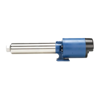
| Type | Submersible |
| Horsepower | 1 HP |
| Voltage | 115/230V |
| Discharge Size | 1-1/4 inch |
| Port Size | 1-1/4 inch |
| Power Cord Length | 20 feet |