8
© Copyright 2016. All rights reserved.
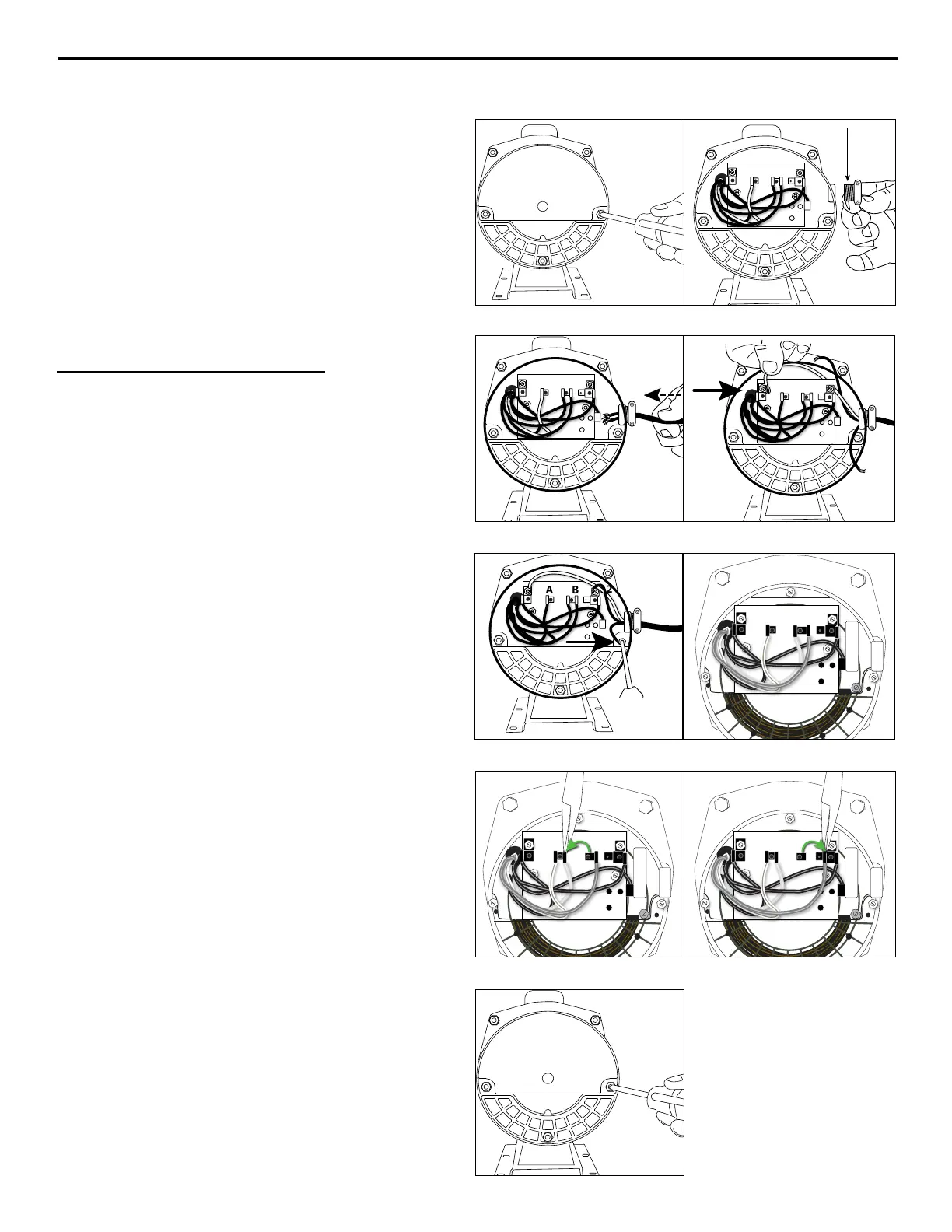
PUMP ELECTRICAL CONNECTIONS
A B
L2
L1
Fig 2Fig 1
A B
L2
L1
A B
L2
L1
Fig 4Fig 3
A B
L2
L1
A B
L2L1
G R AY
RED
Fig 6Fig 5
A B
L2L1
G R AY
RED
A B
L2L1
G R AY
RED
Fig 7bFig 7a
Fig 7c
1. Remove rear motor cover on pump by
unscrewing the two screws.
2. Thread electric wire strain relief into wire
opening on the side of the motor of pump.
3. Insert wire through electric wire strain relief
and tighten screws.
4. Connect white power lead to L1 and black
power lead to L2.
5. Connect green ground wire to green
grounding screw. Re-install rear motor cover
to pump.
To change from 230 V to 115 V
6. The motor of pump is dual voltage and
can run on either 115 volts or 230 volts. In
general, 230 volts is more economical to run,
and requires a smaller wire size. The pump is
pre-set in the factory to run at 230 volts.
7. For 115 volts service, change the following
wires on the terminal board:
a. Using a pair of needle nose pliers, pull the
gray wire with the female flag connector
from the “B” terminal spade post. Place it
to the left on the “A” terminal space post.
b. Pull the red wire with the female flag
connector from the “B” terminal. Place it to
the right on the L2 terminal space post.
c. Reinstall the rear motor cover.
 Loading...