EasyManua.ls Logo

Flint & Walling CJ101D201 - User Manual

Default Icon
11 pages
Print Icon
To Next Page IconTo Next Page
Loading...
1
95 North Oak Street • Kendallville, IN 46755 • Copyright © 2010. All rights reserved.
GENERAL SAFETY INFORMATION
1. Follow all local electrical and safety codes, as
well as the National Electrical Code (NEC) and
the Occupational Safety and Health Act (OSHA).
2. Replace damaged or worn wiring cord
immediately.
3. Do not kink power cable and never allow the
cable to come in contact with oil, grease, hot
surfaces or chemicals.
4. Protect the power cable from coming in contact
with sharp objects.
5. Be careful when touching the exterior of an
operating motor - it may be hot enough to be
painful or cause injury.
6. Make certain that the power source conforms
to the requirements of your equipment.
7. Always disconnect power source before
performing any work on or near the motor or
its connected load. If the power disconnect
point is out-of-sight, lock it in the open position
and tag it to prevent unexpected application
of power. Failure to do so could result in fatal
electrical shock.
8. Do not handle the pump with wet hands or
when standing in water as fatal electrical shock
could occur. Disconnect main power before
handling unit for ANY REASON!
9. Unit must be securely and adequately
electrically grounded. This can be
accomplished by wiring the unit to a ground
metal-clad raceway system or by using a
separate ground wire connected to the bare
metal of the motor frame or other suitable
means.
10.
Risk of electric shock. This
pump has not been investigated for use in
swimming pool areas.
11.
This product contains
chemicals known to the State of California
to cause cancer and birth defects or other
reproductive harm.
NOTE: Pumps with the “CSAmark are tested to
UL standard UL778 and certified to CSA standard
C22.2 No. 108.
OWNERS GUIDE TO INSTALLATION
AND OPERATION
READ THESE INSTRUCTIONS CAREFULLY
Read these installation instructions in detail before installing your pump. Be sure to check the
following:
1. Be certain the motor is connected for the correct line voltage being used (check motor
nameplate).
2. Be certain the pump is completely primed before starting. Otherwise damage may occur to the
seal.
Every pump is tested before leaving the factory, and its performance depends largely on the
installation.
END SUCTION CENTRIFUGAL PUMPS
IL0412
IL0201
Figure 2 - CJ101 SeriesFigure 1 - CJ103 Series
130441
FW0078
0811
Supersedes
0310
Drain Plug
Question and Answer IconNeed help?

Do you have a question about the Flint & Walling CJ101D201 and is the answer not in the manual?

Summary

General Safety Information

Electrical and Handling Warnings

Adheres to electrical safety, warns against wet handling, and highlights chemical risks.

Typical Installations

Pressure Relief Valve Warning

Mandatory installation of pressure relief valve to prevent over-pressure damage and injury.

Pump Installation and Piping

System Gauges and Pressure Relief

Guidance on pressure gauges and the critical need for a pressure relief valve.

Electrical Safety and Wiring

Electrical Connection and Grounding

Mandatory grounding, power cutoff before work, and supply voltage compliance for safe operation.

Pump Priming Procedures

Pump Operation and Motor

Rotary Seal Replacement

Overview

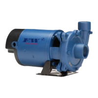
This document provides comprehensive instructions for the installation, operation, and maintenance of end suction centrifugal pumps, specifically the CJ103 and CJ101 series. These pumps are designed for various applications, and proper adherence to these guidelines is crucial for ensuring their optimal performance, longevity, and safe operation.

Function Description

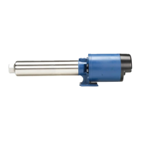
The CJ103 and CJ101 series pumps are end suction centrifugal pumps, meaning they draw fluid in through the end of the pump casing and discharge it centrifugally. They are designed to move liquids by converting rotational kinetic energy into the hydrodynamic energy of the fluid flow. The CJ103 series typically features single-stage operation, while the CJ101 series includes multi-stage units, offering increased pressure capabilities. These pumps are not self-priming, requiring the casing and suction pipe to be completely filled with liquid before starting to prevent damage to the shaft seal. They are suitable for handling clean water and should not be used with dirty or abrasive liquids, which could lead to premature wear and damage.

Usage Features

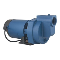
The pumps are designed for versatility in installation, with options for both street supply and well applications. Key usage features include:

  • Voltage Compatibility: Motors are available for single-phase (115V, 230V) and three-phase (208-230/460V) power, with specific wiring diagrams provided for each configuration. It is critical to ensure the motor is connected for the correct line voltage as indicated on the motor nameplate.
  • Priming: As non-self-priming units, thorough priming is essential before initial startup. This involves completely filling the pump casing and suction pipe with liquid. For suction lift installations, a foot valve and strainer are recommended to reduce priming time and maintain prime. A priming tee in the discharge port facilitates filling the pump case.
  • Discharge Port Adjustability (CJ103 Series): The CJ103 series pumps feature a discharge port that can be adjusted in 90-degree increments, allowing for flexible installation to accommodate specific application requirements without affecting pump performance.
  • Pressure Management: The installation of pressure gauges on both suction and discharge pipes is recommended to monitor pump performance, detect issues like cavitation or vapor binding, and ensure stable operation. A pressure relief valve of adequate capacity is mandatory on any installation where pump pressure could exceed the pressure tank's maximum working pressure or in systems where the discharge line can be shut off or obstructed, to prevent extreme overpressure and potential injury or property damage.
  • Piping Recommendations: The use of galvanized piping, rigid plastic, or other suitable pipe that will not collapse under suction or rupture due to pressure is advised. Suction and discharge pipe diameters should match or exceed the pump tappings, with larger pipes recommended for long runs to maintain capacity. All joints and connections should be sealed tightly with Teflon tape or pipe sealing compound.
  • Motor Protection: All single-phase motors include built-in thermal protection that automatically resets after cooling, safeguarding against burnout from overload, low voltage, or high voltage. Three-phase motors, however, require external thermal protection, typically a properly sized magnetic or manual starter with heaters. All motors should be equipped with a correctly fused disconnect switch for protection.
  • Motor Rotation: For single-phase models, rotation is fixed (counterclockwise when facing the pump suction tapping). For three-phase pumps, proper counterclockwise rotation is critical and can be checked by momentarily "bumping" the motor. Rotation can be changed by interchanging any two incoming line leads.

Maintenance Features

The pumps are designed for relatively low maintenance, but certain procedures are essential for their longevity and reliable operation:

  • Lubrication: Both the pumps and motors are designed to be lubrication-free. The motor's ball bearings are pre-greased at the factory and typically do not require further greasing under normal operating conditions.
  • Winterization: To prevent damage from freezing, especially in colder climates, the pump should be removed and stored in a warm environment. If removal is not possible, both drain plugs should be removed to allow complete drainage, and the pump should then be filled with RV-type antifreeze, which also acts as a rust inhibitor.
  • Rotary Seal Assembly Replacement: The mechanical seal is a critical component that may require replacement due to wear or damage. The guide provides detailed disassembly and reassembly instructions, emphasizing careful handling of the precision-lapped seal faces (ceramic and carbon) to avoid nicks, scratches, or dirt, which can significantly shorten seal life. Liquid soap is recommended for ease of installation of the ceramic seat and rubber drive ring. A cardboard washer is suggested for pressing the ceramic seal seat into place to protect its polished face.
  • Motor Replacement: Nema J motors can be replaced in the field with any standard Nema J jet pump motor, following specific instructions for removal and reassembly. It is important to note that damage to the shaft seal is most likely to occur during disassembly, necessitating a new seal during motor replacement.
  • Troubleshooting: A comprehensive troubleshooting chart is provided to diagnose common issues such as little or no discharge, loss of suction, pump vibration/excessive noise, and the pump not starting or running. This chart lists possible causes and corresponding corrective actions, aiding users in quickly resolving operational problems.
  • Gasket and O-ring Care: During disassembly, care should be taken not to damage gaskets or O-rings. If torn or damaged, they should be replaced with new ones to ensure proper sealing and prevent leaks.

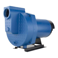
Overall, the CJ103 and CJ101 series pumps are robust devices designed for efficient fluid transfer, with clear guidelines provided to ensure safe installation, effective operation, and straightforward maintenance. Adherence to these instructions is paramount for maximizing the pump's lifespan and performance.

Flint & Walling CJ101D201 Specifications

General IconGeneral
ModelCJ101D201
CategoryWater Pump
Horsepower1 HP
PhaseSingle Phase
Maximum Pressure50 PSI
Maximum Lift25 ft
MaterialCast Iron
Motor TypeTEFC
TypeJet Pump
Voltage115/230V
Inlet Size1.25 inches
Outlet Size1 inch

Related product manuals