Do you have a question about the Flint & Walling PB0508S031 and is the answer not in the manual?
Explains function, applications, and motor types of booster pumps.
Guidance on inspecting the unit for damage after transit.
Details performance data for 60Hz pump models across various HP ratings.
Provides electrical specifications for single-phase 60Hz and 50Hz motors.
Electrical specifications for three-phase motors at different voltages.
Lists components and their materials for standard and stainless steel models.
Specifies wire gauge based on distance, voltage, and HP.
General warnings about hazards, safety labels, and critical safety alerts.
Covers handling, location, suction limitations, and piping recommendations.
Instructions for mounting and securing the pump to a foundation.
Guidance on configuring pressure boosting systems.
Details on installing a sand and sediment trap filter for pump protection.
Illustrates common installations and pressure gauge placement.
Details on selecting voltage and making necessary wiring changes.
Visual guides for connecting single-phase motors to power.
Guidance on valve operation and filling the pump with water.
Specific priming steps for pressure boost installations.
How to verify and set correct rotation direction for motors.
Steps to follow after initial setup for safely starting the pump.
General inspection, cleaning, draining, and lubrication procedures.
Steps for taking the pump apart and replacing the mechanical seal.
Steps for replacing the pump motor unit.
Steps for putting the pump back together after maintenance or seal replacement.
Lists common causes and solutions for pump startup issues.
Addresses problems related to low or no water output from the pump.
Identifies and resolves causes of unusual pump noise and leaks.
Provides an exploded view illustrating all pump parts.
Detailed breakdown of the pump's internal cartridge assembly components.
Lists specific part numbers for 60 Hz pump models.
Lists specific part numbers for 50 Hz pump models.
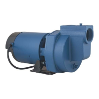
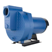
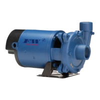
This document provides comprehensive operating instructions and a parts manual for Pressure Booster Pumps, designed to enhance water pressure in various applications.
Pressure booster pumps are engineered to increase water pressure from city mains or private water systems. Their primary function is to provide elevated water pressure for a wide range of uses, including washing buildings, dairy walls or floors, hog parlors, poultry houses, rinsing or spray cooling equipment, lawn sprinkling, and insecticide spraying. These pumps are designed to handle clear water only and are not suitable for pumping dirty water, abrasive liquids, or fluids containing sand, silt, or other abrasives.
Single-phase models are equipped with a capacitor-start, thermal-protected motor, which provides built-in thermal protection against burnout from overload, low voltage, high voltage, and other causes. This device resets automatically once the temperature drops to a safe point. Three-phase models, however, require separate overload protection, typically a properly sized magnetic or manual starter with appropriate heaters.
The pump's operation is automatic when connected to a pressure source like a hydrant or city main, utilizing a contained air pressure tank and pressure switch to prevent rapid cycling and motor overheating. A solenoid valve is recommended for mist spray applications, installed on the discharge side of the pump.
Installation: The installation process emphasizes safety and proper setup to ensure efficient and long-lasting operation. The pump should be located as close as possible to the fluid source, with a short inlet pipe. It must be placed in a dry location, protected from weather extremes, heat, humidity, and freezing temperatures, with ample clearance for air circulation. For permanent installations, the pump should be bolted to a rigid foundation.
Piping is a critical aspect of installation. Galvanized, rigid plastic, or other suitable pipes that will not collapse under suction or rupture due to pressure should be used. If hoses are used, they must be reinforced industrial types rated higher than the system's shutoff pressure. The diameter of the inlet and discharge pipes should match or exceed the pump's ports, with larger pipes recommended for long runs to maintain capacity. Air pockets in inlet piping must be avoided to prevent priming difficulties. Pipe compound or Teflon tape should be used on all joints and connections, ensuring tight seals.
For pressure boost systems, a positive supply of water to the pump must always be maintained. A gate valve and union should be installed in the inlet and discharge lines for service convenience. A check valve, with flow arrows pointing in the direction of water flow, is also necessary. In environments where dirt, sand, or debris is present, a strainer or filter should be installed on the inlet side of the pump, with a trap filter recommended for heavy sediment. Pressure gauges before and after the filter can indicate when cleaning or replacement is needed.
A pressure relief valve must be installed on any system where pump pressure could exceed the pressure tank's maximum working pressure or where the discharge line can be shut off or obstructed, to prevent personal injury or property damage. The unit is not waterproof and is not intended for use in wet locations like showers or saunas. Ambient temperatures around the motor should not exceed 104°F (40°C). For outdoor installations, a cover that allows airflow is required.
Wiring: All wiring must comply with local and United States National Electrical Codes. The motor must be grounded before connecting to the electrical power supply to prevent severe or fatal electrical shock hazards. The ground wire should be connected first to the green grounding terminal on the motor frame, then to a properly grounded service panel or control panel ground bar. Dual voltage motors require changing red and gray wires for the desired voltage. Three-phase motors require proper impeller rotation, which can be checked by momentarily "bumping" the motor with power; rotation can be reversed by interchanging any two incoming line leads.
Operation: Before starting, the pump and inlet pipe must be completely filled with water. The inlet valve should be fully open, and the discharge valve partially open to allow some back pressure during startup. After startup, the discharge valve can be fully opened. During the initial hours of operation, the pump, piping, and auxiliary equipment should be inspected for leaks, excessive vibration, or unusual noises. The pump should not be run dry or against a closed discharge, nor should it pump dirty water or abrasive liquids, as this will cause pump failure and void the warranty. A minimum flow of 1.5 GPM must always be maintained through the pump to keep the pump and seal lubricated.
Routine Maintenance: Routine checks for proper operation are essential. Filters and line strainers should be replaced or cleaned regularly. The pump cannot be completely drained due to its internal design; however, most liquid can be drained by tilting the discharge forward after removing the discharge casting or through the inlet port. Storing the pump in heated areas is recommended. If the pump is used for spraying insecticides, it should be thoroughly flushed with clean water after use. The motor bearings are pre-lubricated and do not require additional lubrication.
Disassembly and Seal Replacement: For pump disassembly, a block of wood, a piece of 3/4" pipe, pipe wrench, strap wrench, 1/4" dowel rod, 9/16" open end wrench, and 3/8" open end wrench are required. The process involves removing the discharge head and loosening the barrel, then sliding the stages off the pump shaft onto a dowel rod. Small 0.010" shim washers may be present near the pump shaft coupling and should be retained for reassembly.
Mechanical seal replacement requires careful handling as the precision-lapped faces are easily damaged. The rotary portion of the seal assembly (carbon ring, Buna-N gasket, and spring) slides off the shaft. The ceramic seal and rubber gasket are pried from the mounting ring. The seal cavity must be thoroughly cleaned. The outer edge of the rubber cup on the ceramic seat should be wet with a minimal amount of liquid soap solution before pressing the ceramic seal half firmly and squarely into the seal cavity, with the polished face upward. If the seal does not seat correctly, a cardboard washer can be used with a 3/4" pipe as a press.
Reassembly: Before reassembling, all component parts of the cartridge assembly should be inspected for damage, wear, or heat distortion. Attention should be paid to the spacing direction of components and the location of shims. Reassembly follows the reverse order of disassembly, with particular care for the rotary seal. Top and bottom o-rings should be checked for damage, and new o-rings are recommended. Pipe compound or Teflon tape should not be used on barrel threads, as o-rings prevent leaks. After reassembly, the discharge head should be tightened to 45-50 ft/lbs, or firmly if a torque wrench is unavailable, avoiding distortion of plastic internal parts. Finally, power should be applied momentarily (15-30 seconds) to ensure the pump and motor rotate freely or with only light rubbing.
Motor Replacement: Motors can be replaced with any standard Nema 56J jet pump motor of the appropriate horsepower. This involves following the steps for rotary seal replacement and pump disassembly, then removing the cap screws connecting the motor to the mounting ring. The new motor is positioned against the mounting frame and secured with four cap screws. A new shaft seal is necessary after motor replacement due to potential damage during disassembly.
| Model | PB0508S031 |
|---|---|
| Category | Water Pump |
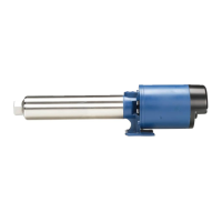
| Type | Submersible |
| Horsepower | 0.5 HP |
| Voltage | 115/230V |
| Material | Cast Iron |
| Phase | Single Phase |
| Suction Size | 1.25 inches |
| Discharge Size | 1.25 inches |