22
Chapter 3
connected on the network for continuous
monitoring and data logging via PC or
PLC control. Typically, the telnet protocol,
accessed by the Windows
®
PC running
the application program, is used to query
the camera for data. This protocol is also
available for most PLCs. In either case, this
takes place though the camera’s Resource
Socket Services. (Command syntax is
contained in the camera’s ICD manual; a
few examples are listed in Appendix D.)
The system designer or FLIR would
create the message instructions that
allow the PLC to query the camera for
temperature data and thermographic
images in the same way it is done with PC
control. Alternatively, the PLC can hold
the Ethernet port open and call for the
camera to continuously output data to
this port at the maximum rate possible. In
either case, alarm functions and decision-
making is performed by the application
program running on the PLC (or PC if
applicable). (See Figure 6.) Typically,
temperatures and images collected for
trend analysis and statistical process
control purposes are stored on a separate
server connected to the network, which
is running transaction manager software
for downloading and storing data.
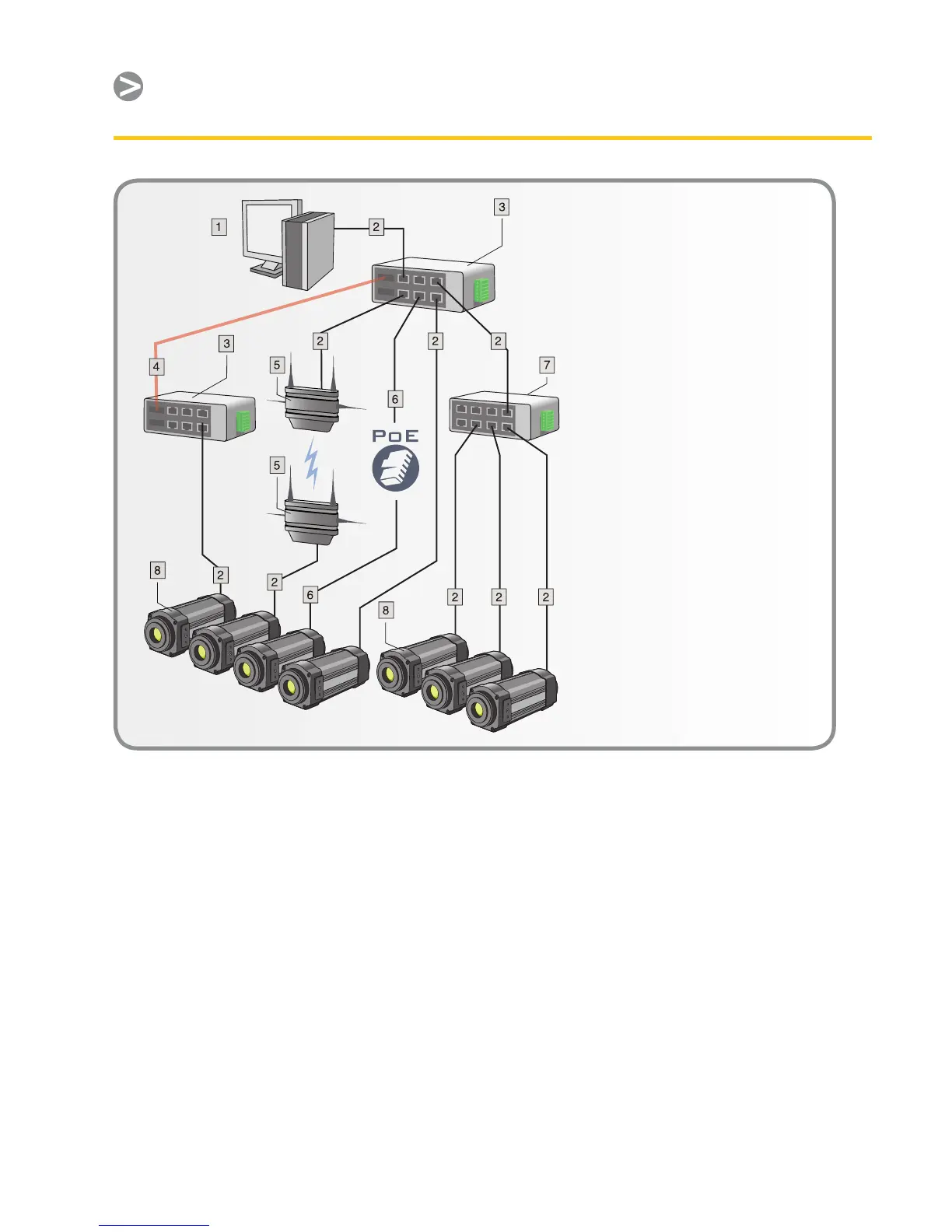
1 Computer, PLC, and/
or transaction manager
server
2 CAT-6 Ethernet cable
with RJ45 connectors
3 Industrial Ethernet
switches with ber optic
ports
4 Fiber optic cable
Wireless access points
6 CAT-6 Ethernet cable
with RJ45 connectors.
Powering the camera
using PoE (Power over
Ethernet)
7 Industrial Ethernet
switch
8 ThermoVision A320
cameras monitoring a
process or other target
objects
Figure 6. Generalized IR machine vision system and its communications network