21
Temperature Measurement for Automated Processes
compressed (MPEG-4) streaming video
can be available for monitoring on a PC
screen. With FLIR’s A320 camera, images
and alarms can be sent to a remote PC via
TCP/IP and SMTP (email) protocols.
While a visible light camera may be able
to detect broken ber strands, an IR
camera can also provide temperature
measurements for trending and statistical
process control (SPC) purposes. In
addition, some textile processes create
steam or condensation vapors that a
visible light camera cannot see through,
but an IR camera can. Thus, an IR camera
provides multiple functions and is more
cost eective.
Data Communications and
Software Considerations
Dierent cameras have dierent video
frame rates. The frame rate governs how
frequently the thermographic image
and its temperature data are updated.
A typical rate might be every 200ms or
so. The camera’s digital communications
protocol could create a small amount of
additional latency in the update process.
Still, because process temperatures tend
to change slowly, collecting temperature
data at this rate provides a wealth of
information for quality control purposes.
In many IR cameras there is some sort
of serial/socket interface that can be
used for communications with the PC
or PLC that is running a control script,
or application. When a system designer
or user is most familiar with PLCs, the
control algorithm can be built around
a virtual PLC created on a PC, which
emulates actual PLC hardware and logic.
In any case, a human-machine interface
(HMI) is created to monitor data coming
from the camera. The details described
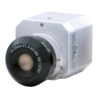
below are based on FLIR’s A320 camera,
but should be representative of most
cameras that transmit data over an
Ethernet link.
The only physical interface for digital
data transfer from the FLIR A320 is the
Ethernet port. Only TCP/IP is supported,
but the camera should work seamlessly
on any LAN when the proper IP address,
netmask, and possibly a gateway is set
up in the camera. The two main ways
of controlling the camera are through
the command control interface and the
resource control interface. Digital image
streaming, data le transfer, and other
functionality is provided through the
IP services interface. A lot of software
functionality is exposed through
software resources. These resources
can be reached through the FLIR IP
Resource Socket Service. This is the
camera’s resource control (serial/socket)
interface. Independent of the physical
Ethernet interface, it is possible to access
the camera system using TCP/IP with
telnet, ftp, http, and FLIR Resource Socket
Services (among others).
Most PLCs provide serial/socket interfaces
for Ethernet. One example is Allen-
Bradley’s EtherNet/IP Web Server Module
(EWEB for short). Another example is HMS
Industrial Network’s Anybus X-Gateway
Ethernet interface module, which can
convert this serial socket interface to
many industrial network protocols, such
as EtherNet I/P, Modbus-TCP, Pronet,
Ethernet Powerlink, EtherCAT, FLNet., etc.
Camera setup and data acquisition is
normally done directly through the FLIR IR
MONITOR and IP CONFIG software running
on a PC. Afterward, the camera can be

 Loading...