EasyManua.ls Logo

Flow Safe F88 Series - User Manual

Flow Safe F88 Series
15 pages
Print Icon
To Next Page IconTo Next Page
Loading...
F88 SERIES
SAFETY RELIEF VALVE
PLASTIC SEATED
- 3, - 4, - 8, - G, - J Orifices
(WITH BOLTED BONNET)
INSTALLATION,
OPERATION, & MAINTENANCE MANUAL
Revision: D
Date of Issue: Feb. 2, 2016
Approved by: GG jwo
Project Engineer Engineering Projects Dir.
Question and Answer IconNeed help?

Do you have a question about the Flow Safe F88 Series and is the answer not in the manual?

Overview

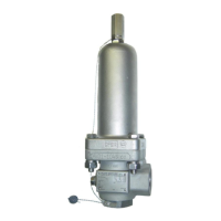
The document describes the F88 Series Safety Relief Valve, a direct-acting spring-loaded relief valve manufactured by Flow Safe. This manual provides guidance for the installation, operation, and maintenance of the valve.

Function Description:

The F88 Series Safety Relief Valve is designed for both gas and liquid service, providing overpressure protection for systems. It operates by opening when the inlet pressure exceeds a preset value, releasing excess fluid to prevent damage to the system. The valve is plastic-seated with a plastic seal, contributing to its sealing characteristics.

Important Technical Specifications:

  • Orifice Sizes: Available in -3, -4, -8, -G, and -J.
  • Set Pressure Range:
    • Minimum Set Pressure (All Body Sizes): 50 psig (3.5 barg).
    • Maximum Set Pressure:
      • C, D, E Body with standard bonnet: 720 psig (49.6 barg) for -3, -4, -8 orifices; 668 psig (46 barg) for -G orifice; 298 psig (20.5 barg) for -J orifice.
      • C, D, E Body with XL bonnet: 4292 psig (296 barg) for -3, -4, -8 orifices; 3705 psig (255 barg) for -G orifice; 2700 psig (186 barg) for -J orifice.
      • C Body with XXL bonnet (Liquid only): 8382 psig (578 barg) for -3, -4 orifices.
  • Blowdown: Non-adjustable, approximately 20% of set pressure. For low flow rates on liquids, the valve tends to modulate and reclose with this approximate blowdown value.
  • Soft Goods Temperature Range (F88 Seats & Seals):
    • PI/PAI/Vespel: MAX 500°F (260°C), MIN -423°F (-252°C).
    • PEEK: MAX 525°F (273°C), MIN 0°F (-18°C).
    • Teflon (PTFE): MAX 400°F (204°C), MIN -423°F (-252°C).
    • Kel-F (PCTFE): MAX 400°F (204°C), MIN -423°F (-252°C).
    • F88 Seals (Teflon PTFE): MAX 400°F (204°C), MIN -423°F (-252°C). (Note: Confirm service/application with factory for minimum temperatures).
  • Set Pressure Tolerances:
    • 70 psig: ± 3% of specified set pressure.

    • ≤ 70 psig: ± 2 psi.
  • Seat Tightness (ZERO leakage with inlet pressure at or below):
    • Gas service: 0.90 x set pressure.
    • Liquid service: 0.90 x set pressure (if set pressure > 100 psig); 0.80 x set pressure (if set pressure < 100 psig).
  • Corrosion Allowance: 0.06" (1.5 mm) designed into all carbon steel components subject to corrosion.

Usage Features:

  • Installation:
    • Should be installed in an upright position, as close as possible to the pressure source to minimize pressure losses.
    • Inlet piping pressure losses should not exceed 3% of the set pressure when the valve is flowing (API 520 Part II recommendation).
    • Discharge pipe should be sufficiently large to prevent backpressure from exceeding system design conditions.
    • F88 Series valves are balanced against superimposed backpressure, meaning the set pressure will not change with backpressure.
    • Inlet piping/flanges should have an opening equal to or greater than the valve's inlet diameter, free of obstructions.
    • Use wrench flats on the valve inlet bushing for tightening and installation; do not wrench on the cast body or bonnet.
  • Startup:
    • Piping must be thoroughly cleaned prior to installation to prevent damage from foreign particles.
    • If a block valve is used, it must be opened before pressurizing the system and locked open during normal operation.
    • Verify valve seat is leak-tight according to Section 4.4.
  • Lift Lever Operation:
    • The lift lever allows verification that the valve spindle and seat can open freely, but does not verify set pressure.
    • Do not operate the lift lever unless valve inlet pressure is at least 75% of the nameplate set pressure.
    • Rotate the handle clockwise or counterclockwise until resistance is met, then slowly continue until flow is indicated.
    • If inlet pressure is greater than reseat pressure (approx. 80% of set pressure), the valve may develop full flow and stay open until blowdown pressure is reached.

Maintenance Features:

  • Regular Maintenance Schedule: Flow Safe recommends regular maintenance, including routine replacement of softgoods, typically every three years, though customers should determine their own schedule based on use and environment.
  • Internal Component Inspection: During maintenance, internal components should be inspected for damage, abnormal wear, and excessive corrosion.
  • Cycling: Cycling the valve at least once a year is considered good practice to verify operation and confirm parts are not seized.
  • Softgoods Kits: Available for different orifice sizes and seat materials (PTFE/Teflon, PCTFE/Kel-F, PI/PAI/Vespel, PEEK, Ekonol-filled Teflon). Bushing seal and rear seal are Teflon.
  • Disassembly: Detailed steps are provided, including removing lockwire, lift lever components (if applicable), pressure adjusting screw cap, bolts, nuts, lockwashers, spring, bonnet, bushing, spindle assembly, retainer screw, retainer, seat, and spindle cap.
  • Reassembly: Detailed steps are provided, essentially the reverse of disassembly, with emphasis on careful handling of softgoods, inspection of seating and guide surfaces, proper installation of seals and seats, and correct torque values for bonnet bolts. Lubricants (Neverseez or DuPont Krytox for oxygen service) should be used on straight threads. Desco 600 grease (or Dow Corning 33 or 55/Molykote for cryogenic service or valves below 100 psig) should be applied to the outside of the spindle seal.
  • Testing and Adjustment:
    • Set pressure and seat tightness are necessary tests. Blowdown is non-adjustable.
    • Gas service valves should be set using air; liquid service valves using water or other suitable liquid.
    • Set pressure adjustment involves loosening the PA screw lock nut and screwing the PA screw in/out until the desired pop (gas/vapor) or gush (liquid) pressure is achieved.
  • Troubleshooting Guide: Provides symptoms, possible causes, and remedies for common issues such as leaks (around bushing, outlet, atmospheric vent), valve not closing, valve opening below/above set point, and valve chatter/rapid-cycling. Remedies include tightening, inspecting/polishing surfaces, replacing damaged parts, adjusting pressure, and checking piping.
  • Warranty: Any stated or implied warranties are null and void if the valve is disassembled by someone other than approved Flow Safe personnel. All repairs and resetting of "UV"-stamped safety relief valves should be performed by Flow Safe, Inc., or a National Board-certified valve repair shop holding a "VR" stamp.

Flow Safe F88 Series Specifications

General IconGeneral
BrandFlow Safe
ModelF88 Series
CategoryControl Unit
LanguageEnglish

Related product manuals