Do you have a question about the Flow-tronic Raven-Eye and is the answer not in the manual?
Details safety warnings, symbols, and precautionary labels, including R&TTE regulations.
Explains warning symbols like DANGER, WARNING, CAUTION, and IMPORTANT NOTE.
Details safety alert symbols and specific labels like WEEE, electrical shock, ground, fuse, and ESD.
Defines confined spaces and outlines safety precautions and explosion hazards.
Lists conditions for using the device regarding R&TTE directives and user responsibilities.
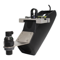
Describes the RAVEN-EYE® sensor's function and design for open channel flow measurement.
Explains how radar measures surface velocity and ultrasonic sensors measure level for flow calculation.
Guides on inspecting the instrument upon delivery and lists standard delivered items.
Covers site selection, sensor mounting, and alignment procedures.
Provides guidelines for selecting an optimal installation location in a channel for accurate measurements.
Details the process of installing the sensor, including mounting and alignment.
Details steps for installing the mounting hardware on the manhole wall.
Outlines the procedure for attaching the RAVEN-EYE® sensor to the mounting hardware.
Guides on vertically aligning the sensor without a level sensor.
Provides instructions for attaching the optional level sensor.
Details vertical alignment of the sensor when the level sensor is attached.
Explains how to horizontally align the sensor for accurate flow measurement.
Describes the process for verifying vertical and horizontal sensor alignment.
Details how to measure the sensor offset for accurate flow calculations.
Formulas and examples for calculating sensor offset for specific level sensors.
Guides on measuring the pipe diameter for accurate flow rate calculations.
Provides information on connecting the sensor to external devices.
Provides recommendations to prevent ESD damage to the instrument's electronic components.
Details the connections for the RAVEN-EYE® sensor to a PLC or controller.
Refers to the UNI-TRANS manual for wiring and operation.
Refers to the RTQ-Logger Series manual for wiring and operation.
Explains the Modbus ASCII communication protocol for the RAVEN-EYE® sensor.
Explains the Modbus ASCII communication protocol for the RAVEN-EYE® sensor.
Routine checks for sensor condition, enclosure integrity, and electrical connections.
Instructions on how to clean the sensor, typically after a surcharge event.
Step-by-step guide for replacing the sensor's cable.
Contact details for Flow-Tronic S.A. within Belgium and Luxembourg.
How to find a representative or distributor outside Belgium and Luxembourg.
Contact information for technical and customer service assistance.
Procedure for returning a device for repair, including authorization.
Instructions for completing the customer registration form.
Details safety warnings, symbols, and precautionary labels, including R&TTE regulations.
Explains the meaning of various safety symbols used in the manual.
Details specific safety labels found on the equipment and their significance.
Addresses hazards and safety protocols for operating the device in confined spaces.
Lists conditions and compliance requirements related to R&TTE directives.
Explains the working principles of the RAVEN-EYE® sensor for velocity and level measurement.
Instructions for unpacking and inspecting the RAVEN-EYE® sensor and its accessories.
Covers site selection, sensor mounting, and alignment procedures.
Guidelines for choosing the best location to install the sensor in a channel or pipe.
General guidance on installing the RAVEN-EYE® sensor above the open channel.
Step-by-step instructions for mounting the hardware on the manhole wall.
Details on how to connect the RAVEN-EYE® sensor to the installed mounting hardware.
Instructions for achieving vertical alignment of the sensor when no level sensor is attached.
Procedures for attaching the optional level sensor to the mounting hardware.
Steps for vertical sensor alignment with the level sensor attached.
Guidance on ensuring the sensor is horizontally centered over the flow.
Procedure to confirm correct vertical and horizontal sensor alignment for accuracy.
Method to measure the sensor offset, crucial for flow calculations.
Formulas and examples for calculating sensor offset for specific level sensors.
Instructions for accurately measuring the pipe or channel diameter.
Information on connecting the RAVEN-EYE® sensor to external devices like PLCs.
Best practices to prevent damage from static electricity during handling and maintenance.
Details the wiring color codes and connections for the RAVEN-EYE® sensor.
Refers to the UNI-TRANS manual for operational details.
Refers to the RTQ-Logger Series manual for operational details.
Explains the Modbus ASCII communication protocol for the RAVEN-EYE® sensor.
Explains the Modbus ASCII communication protocol for the RAVEN-EYE® sensor.
Lists communication characteristics and Modbus functions used by the sensor.
Details Modbus registers for reading measurement data from the sensor.
Describes Modbus registers for reading and writing level input data.
Routine checks for sensor condition, enclosure integrity, and electrical connections.
Instructions on how to clean the sensor, typically after a surcharge event.
Step-by-step guide for replacing the sensor's cable.
Contact details for Flow-Tronic S.A. within Belgium and Luxembourg.
How to find a representative or distributor outside Belgium and Luxembourg.
Contact information for technical and customer service assistance.
Procedure for returning a device for repair, including authorization.
Instructions for completing the customer registration form.
| Brand | Flow-tronic |
|---|---|
| Model | Raven-Eye |
| Category | Measuring Instruments |
| Language | English |