Rue J.H. Cool 19a | B-4840 Welkenraedt | BELGIUM
Tel. : +32 (0)87 899 799 | Fax : +32 (0)87 899 790
E-mail : info@flow-tronic.com | www.flow-tronic.com
- 24 -
4 Operation
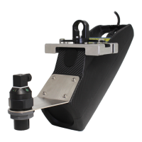
The RAVEN-EYE
®
sensor is meant to be operated with different logger and monitor types.
Use the RAVEN-EYE
®
sensor in combination with the UNI-TRANS monitor for stationary or hybrid applications.
The RAVEN-EYE
®
connects directly to the UNI-TRANS monitor and the basic configuration can be made using the
programming keys on the device.
Use the RAVEN-EYE
®
sensor in combination with one of the following RTQ-Loggers: RTQ-500, RTQ-1000 or
RTQ-2000 for portable applications or applications where no power source is present on site. The RAVEN-EYE
®
connects directly to the portable logger and the configuration of the sensor and the measuring site is made with the
RTQ-Log configuration software or directly through our 123Flow.com web platform using a GPRS communication.
The RAVEN-EYE
®
has also been developed for direct connection to any PLC, controller or logger equipped with a
RS485 communication port supporting the Modbus ASCII protocol. This solution is ideal for integrators and enables
to read different registers in the RAVEN-EYE
®
such as average velocity, flow, level, quality parameters, etc. The
measuring site and the RAVEN-EYE
®
are configured connecting the sensor to a computer using the USB
configuration cable (optional) and the RTQ-Log software.
Converters are available for use with Modbus RTU, please contact our service department for more information.
Contact information is available in section7.3 on page - 28 -.
4.1 UNI-TRANS
Refer to the UNI-TRANS installation & operation manual for wiring and operation.
4.2 RTQ-Logger Series
Refer to the RTQ-Logger Series (RTQ-500, RTQ-1000 or RTQ-2000) installation & operation manual for wiring and
operation.
4.3 MODBUS ASCII
4.3.1 How does it work?
In order to read the different registers using the Modbus ASCII protocol from the RAVEN-EYE
®
sensor, you need a
PLC or controller with a RS485 communication port and a 4-20 mA input. The PLC will act as the “master” unit.
Connect the level sensor (ULS-02, ULS-06 or other) to the 4-20 mA input of the PLC. The PLC will send the level
information to the RAVEN-EYE
®
sensor and the RAVEN-EYE will calculate the flow based on different parameters
it has. The PLC can then read the different registers (refer to Table 2 on page - 25 -) from the RAVEN-EYE
®
.
All the parameters from the measuring site are configured using the RTQ-Log software. Refer to the RTQ-Log
software installation & operation manual for instructions.
 Loading...