the offset on the new gas valve to guarantee a correct
operation of the water heater.
Instructions as follows:
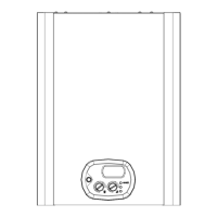
Fig. 1 – Disconnect the silicon pipe from its connection
i
onto the venturi air intake point.
Fig. 2 – Connect that end of the silicon pipe to a ‘T’
connection
T
and bring the end of another silicon pipe from
the same ‘T’ connection to the venturi air intake point
i
.
Insert a third silicon pipe on the free connection of the ‘T’
and connect its end to the negative point
-
of a gas
pressure manometer.
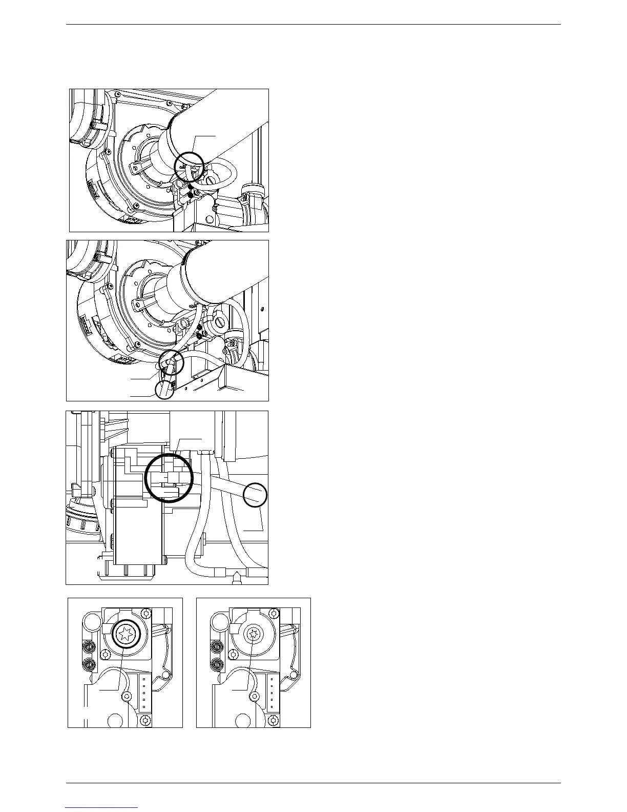
Fig. 3 – Unscrew the pressure
p
point screw and connect
there the pipe that goes to the positive point
+
of the gas
pressure manometer.
Switch the water heater On at the minimum power. The
manometer should read a value of
-
0.04 mbar
; if you read
a different value, proceed as follows (Fig.4)
Fig. 4 – Remove the protection cover
manometer and to bring it to
-
0.04 mbar
.
Once the regulation is completed, disconnect
pipes and restore original water heater
configuration.