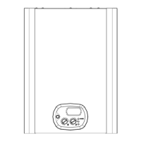
Safety thermostat (see fig. 1)
• Disconnect the connecting wire;
• Unscrew the fixing screws and remove the
thermostat;
• Replace the thermostat and re-assemble the
components following the above procedure in
reverse order;
• Switch on the electricity, water and gas supplies and
restart the appliance.
Heating sensor (see fig. 1)
• Un-Plug the connecting wire;
• Replace the sensor and re-assemble the
components following the above procedure in
reverse order;
• Switch on the electricity, water and gas supplies,
open the shut-off valves and fill the central heating
circuit. Then restart the appliance, remembering to
discharge any air that may be trapped in the system;
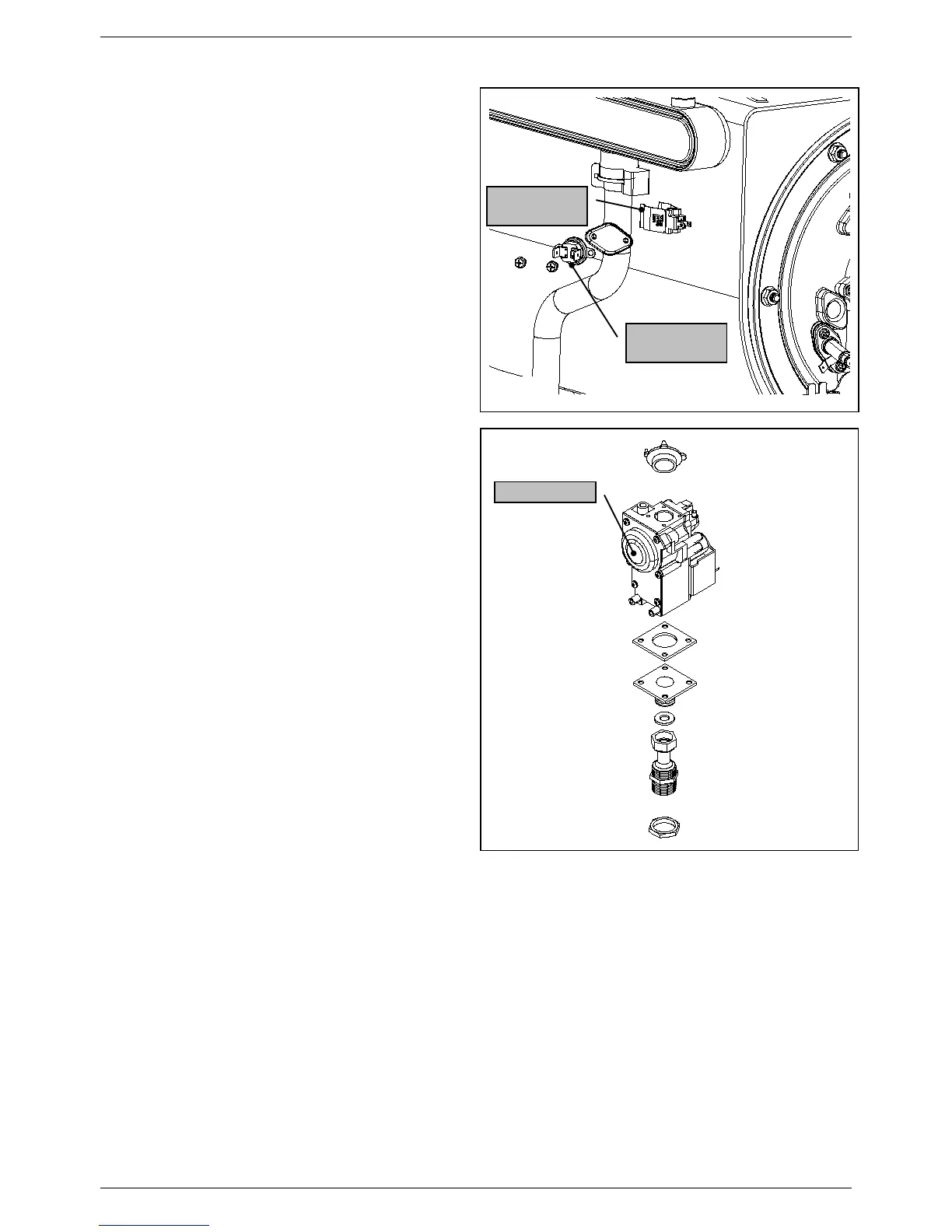
Gas valve
(see fig. 2)
• Unscrew the screws connecting the gas valve to the
venturi.
• Disconnect the gas feed pipe and valve ring-nut at
the bottom of the room-sealed chamber.
• Remove the flanged elbow coupling of the existing
valve and fit it to the new valve; also fit a new cork
washer and a new rubber gasket.
• Replace the gas valve and re-assemble the
components following the above procedure in
reverse order.
• Replace all the gas seals.
• Fully tighten the gas connections.
• Switch on the electricity, water and gas supplies and
check for any gas leaks using a soapy solution or
leak detector spray;