Regulating the Flow temperature in accordance with the outdoor temperature
The outdoor sensor has to be connected directly to circuit board SM 20021. The sensor can thus be managed in
one of two ways:
• In case of remote controller + outdoor temperature sensor installation, the climatic compensation curve is set by
the remote itself (see remote control installation and operating manual).
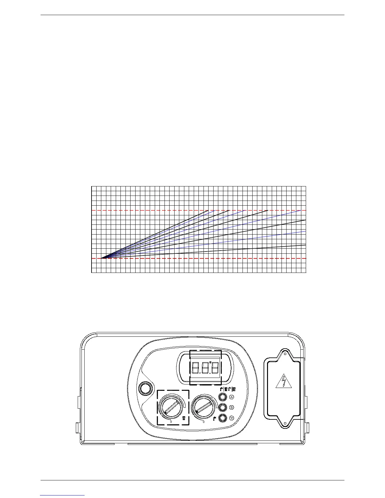
• In case of outdoor temperature sensor only installation, the climatic compensation curve is set using the central
heating control knob. As the knob (see fig. 2) is rotated, the numbers corresponding to the curve shown in figure
1 are displayed
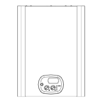
The factors governing the correction are reported in figure 1.
The selection of the compensation curve is determined by the maximum delivery temperature Tm and the minimum
outdoor temperature Te.
N.B. The y-axis values of the delivery temperature Tm refer to standard 167-86 °F appliances or 104-77 °F floor-
mounted appliances. The type of appliance can be programmed using parameter 3 (see 5.1 “Parameter
programming”).
55
OUTDOOR SENSOR
DELIVERY TEMPERATURE CORRECTION AS A FUNCTION OF OUTSIDE
TEMPERATURE WITH RESPECT TO THE POSITION OF THE HEATING
TEMPERATURE CONTROL SET BY THE USER
TM-MAX/MIN = delivery temperature range selected
158
95
MIN
77
81 79
86
86
95
113
104
122
140
131
149
66
7577
73 7072 68 6164 63 59
57
Tm
MAX
104 176
167
Te = Outdoor temperature Tm = delivery temperature
1050
54
52 4648
45
4143 39 3637 34 21273032 28 25 23 1619 18 14 12
8
9
7
6
5
0
Te (°F)
5
9
7
1
2
3
4