Worcester 13 / 14 Series User Instruction – WCENIM0002-01
Page 6 of 13
5 Installation
5.1 Preparation
a) The working area should be clean and clear of any debris that would
contaminate the valve.
b) When despatched, valves contain a mineral oil which aids the bedding in of the
valve. This may be removed if found unsuitable. Special variants may contain
other lubricants or be dry built.
c) Some valves contain a silica gel pack inside the ball cavity to absorb humidity
during storage. These must be removed before installation along with all other
protective packaging.
d) The gland nut locking clip must be retained at all times. During installation, if the
locking clip is not in place, the gland nut must be adjusted to the correct torque
and a new locking clip must be fitted.
e) Significant problems can arise with any valve installed in an unclean pipeline.
Ensure that the pipeline has been flushed clean of dirt, weld spatter etc. before
installation.
f) Graphite seals should be handled with care due to their delicate nature.
g) If transit seals are fitted inside the valve, these must be discarded and replaced
with the spare body seals supplied.
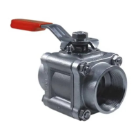
5.2 Installation
a) It is recommended that the valves are in the open position during fitting.
b) Screwed end valves:
Do not dismantle these valves to install. Ensure that the pipeline and valve
threads are clean. Apply a suitable thread sealant to the pipe threads
and screw into the valve being careful not to over-tighten tapered
threads. Do not use the valve wrench or stem as a lever to tighten the
valve onto the pipe thread.
c) Weld end valves:
Fully assembled weld end valves (butt and socket), must only be tack-
welded into position, as the full weld heat will damage the seats and seals.
After tack welding, remove the body assembly as per section 9.1.
Complete the welding procedure after protecting the connector end
faces from weld spatter.
When cool, clean the valve connector end faces and then fit the new
body seals (supplied) into the body. Reassemble the valve as per section
9.2.