EasyManuals Logo

Flowserve 13 Series User Manual

Flowserve 13 Series
14 pages
To Next Page IconTo Next Page
To Previous Page IconTo Previous Page
Page #12 background imageLoading...
Page #12 background image
Worcester 13 / 14 Series User Instruction WCENIM0002-01
Page 11 of 13
10 Technical Data
10.1 Gland nut torque
The torque to be applied to the gland nut to ensure the correct amount of stem
sealing.
10.2 Stem assembly torque
The torque required to operate the assembled stem before the ball and seats are
fitted to the valve.
10.3 Connector bolt torque
The torque required to give a metal-to-metal contact between the body and the
inner surface of the body connectors.
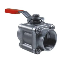
10.4 Torque data
Table 2 Torque Data
Size
(Reduced
Bore)
Size
(Full
Bore)
Gland
nut PTFE
build
(Nm)
Stem
assembly
(Nm)
Connector
bolts (Nm)
Connector
cap
screws
(Nm)
DN 20
DN 15
6 9
3 5
13 15
25 29
DN 25
DN 20
8 12
4 6
24 28
27 31
DN 40
DN 32
13 18
6 8
33 37
35 39
DN 50
DN 40
13 18
6 8
38 42
49 53

Questions and Answers:

Question and Answer IconNeed help?

Do you have a question about the Flowserve 13 Series and is the answer not in the manual?

Flowserve 13 Series Specifications

General IconGeneral
BrandFlowserve
Model13 Series
CategoryControl Unit
LanguageEnglish

Related product manuals