FlowAct Diaphragm Linear Actuator FCD VLENIMFACTA4 10/16
16
Reassemble the Actuator onto
the valve:
1. Mount the actuator onto the bonnet and tighten the
yoke lock nut (76) clockwise.
NOTICE
The legs of the yoke should be parallel
to the flow direction.
2. Move the actuator to the open position.
3. Screw in the lock nut (113) onto the valve stem so it
is screwed all the way and lower coupling (345) three
turns and move the actuator into the closed position.
NOTICE
The plug must be aligned onto the
seat. The cushioning effect of the bel-
lows can be prevented by tightening the packing follower.
4. Move the actuator back into the open position and
adjust the distance between the lower coupling (345)
and upper coupling (249) by adjusting the stroke length.
Valve size Stroke
15 - 25 1/2“ - 1“ 10
+ 0,5
mm 0.394
+ 0.02
in.
15 - 50 1/2“ - 2“ 20
+ 0,5
mm 0.787
+ 0.02
in.
65 - 100 3“ - 4“ 40
+ 0,5
mm 1.574
+ 0.02
in.
125 - 150 6“ 60
+ 0,8
mm 2.362
+ 0.03
in.
200 - 300
1)
8“ - 12“
1)
80
+ 0,8
mm 3.150
+ 0.03
in.
400 16“ 100
+ 0,8
mm 3.937
+ 0.03
in.
Table 11: Stroke adjustment length (
1)
depends on the valve
series)
5. Move the actuator to the close position and install the
cap screws (240).
6. Lock the lock nut (113). Keep upper coupling (249)
from turning by securing with a wrench.
7. If a handwheel-side was mounted reassemble as next
(see pages 37 - 38).
NOTICE
The handwheel-side always presses
on the coupling, depending on the
safety position when actuated. The lever arms must be
positioned so that this condition is given.
8. Place the handwheel-side on the yoke and straighten
it, mount the washer (140) and hex bolt (150) and
tighten it, if applicable.
9. Check handwheel-side for correct limit position, if
applicable.
10. Reassemble the accessory on the valve as necessary,
see relevant accessory User Instruction.
11. Perform three full strokes and check the free movement
of the actuator.
12. For installation the valve into the pipeline and further
steps see User Instructions for applicable valve types.
13. Log the maintenance interval and the work performed.
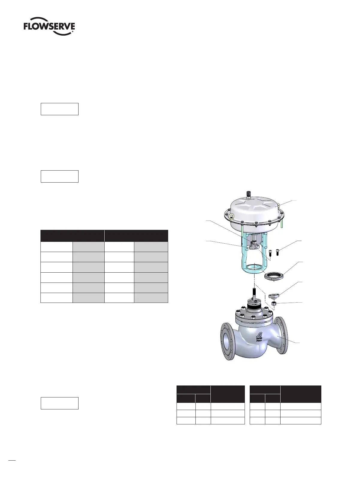
Actuator
240
76
345
113
Valve
249
344
Figure 9: Yoke assembly drawing
Item
Part
Item
Part
WW
EU
WW EU
76 5.10 Yoke lock nut 249 5.3 Upper coupling
113 5.2 Lock nut 344 5.4 Lock nut
240 5.5 Cap screw 345 5.1 Lower coupling
Table 12: Coupling parts identification