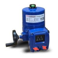
Limitorque Actuation Systems L120 Series FCD LMENIM1201-05-A4 – 03/18
10
4.2 Safety Practices
The following checks should be performed to maintain safe operation of the L120 actuator.
• Mount motors on a horizontal plane, if possible.
• Keep the controls compartment clean and dry.
• Keep the valve stem clean and lubricated.
• Set up periodic operating schedule for infrequently used valves.
• Carefully check for correct motor rotation direction. If the motor is driving the valve in the wrong
direction, interchange any two leads on three-phase motors or switch the armature leads on DC and
single-phase motors.
• Use a protective stem cover. Check valve stem travel and clearance before mounting covers on rising
stem valves.
• Verify all actuator wiring is in accordance with the applicable wiring diagram, national and local codes,
and Table 4.1.
Table 4.1 – Required Rating for External Wiring
Up to: Use wire rated at least:
40°C 60°C
60°C 75°C
4.3 Initial Actuator Preparation
Replace all molded plastic conduit and top protectors (installed for shipping purposes only) with pipe
plugs when installation wiring is complete.
4.3.1 Mounting Base
The mounting hole sizes and quantities are as detailed in Table 4.2.
Table 4.2 – Mounting Base Dimensions
Actuator Size
Mounting Holes Tap size
Quantity MSS ISO
L120-10 4
3
⁄8-16x0.88 M10x1.5x22.4
L120-20 4
5
⁄8-11x1.25 M16x2x32
L120-40 4
5
⁄8-11x1.25 M16x2x32
4.3.2 Stem Acceptance
The maximum stem acceptance is provided in Table 4.3.
Table 4.3 – Maximum Stem Acceptance
Actuator size
Drive 2 Drive 1
Tapped Bore Key
inch mm inch mm inch mm
L120-10 1.25 32 1.00 25 ¼x3/32 8x6
L120-20 2.25 57 1.875 47 ½x3/16 14x9
L120-40 2.625 66 2.125 52 ½x3/16 16x10
 Loading...
