2 of 5
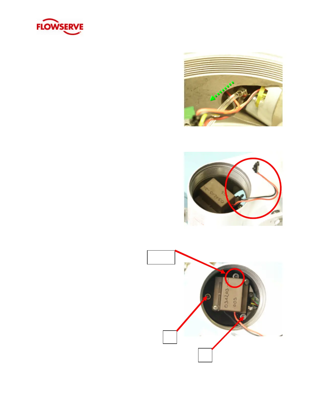
4. Disconnect the flexible tubing from the
barbed fitting on the driver module assembly
by hand.
5. Pull the red and black 2-wire piezo connector
through bottom of driver module housing.
6. Loosen and remove the 9/64” Allen screws A
and B. Important: Loosen the screw
opposite the wire entry last. This screw is
retained by the piezo cover, and should only
be removed after screws A & B are removed
to avoid damaging the cover.
LAST
A
B

 Loading...


