EasyManua.ls Logo

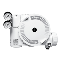
Flowserve Logix 520MD+ User Manual

Flowserve Logix 520MD+
84 pages
To Next Page IconTo Next Page
Page #1 background imageLoading...
Page #1 background image
Experience In Motion
USER INSTRUCTIONS
Installation
Operation
Maintenance
Logix
®
520MD+ and 510+
Digital Positioners
FCD LGENIM0105-15-AQ – (05/16)

Table of Contents

Questions and Answers:

Flowserve Logix 520MD+ Specifications

General IconGeneral
TypeDigital Valve Positioner
Input Signal4-20 mA
Output SignalPneumatic
Communication ProtocolHART
Enclosure RatingIP66/NEMA 4X
Housing MaterialAluminum
CertificationsATEX, IECEx, CSA, FM
Supply Pressure1.4-7 bar (20-100 psi)
Air ConsumptionTypically less than 0.12 Nm3/h at steady state
Operating Temperature-40 to 85 °C
MountingDirect mounting on linear and rotary actuators

Summary

General Information

Terms Concerning Safety

Definition of safety terms like DANGER, CAUTION, and NOTE for hazard communication.

Service / Repair

Highlights safety during service/repair and consequences of modification.

Basic Operation

Overview of the Logix 500+ digital positioner's function and capabilities.

Specifications

Input Signal Specifications

Details input signal specifications, power supply, and resistance.

Pneumatic Output Specifications

Specifies output pressure range and air capacity for different relays.

Air Supply Requirements

Outlines air supply requirements, quality, and consumption.

Analog Output Specifications

Specifications for the 4-20 mA analog output function on the Multi-Function Card.

Positioner Performance Characteristics

Performance metrics like resolution, linearity, repeatability, and hysteresis.

Hazardous Area Certifications

Mounting and Installing

Mounting to Mark One Linear Valves

Step-by-step guide for mounting the positioner to Mark I Linear Valves.

Mounting to FlowTop Linear Valves

Instructions for mounting the positioner to FlowTop Linear Valves.

Mounting to Standard Valtek Rotary Valves

Guide for mounting the positioner to standard Valtek rotary valves.

Mounting to Maxflo Rotary Valves

Steps for mounting the positioner to Maxflo rotary valves.

Mounting to Rotary NAMUR (AutoMax) Valves

Procedure for mounting the positioner to Rotary NAMUR (AutoMax) valves.

Mounting to a Linear NAMUR Pneumatic Actuator

Mounting instructions for the positioner to linear NAMUR pneumatic actuators.

Tubing Connections

Determine Air Action

How to determine and set air action (open/close) based on actuator tubing.

Connect Supply Port

Guidance on connecting the air supply port and filter recommendations.

Electrical Connections

Command Input (4-20 mA) Connection

Connecting the 4-20 mA current source for command input.

Compliance Voltage Requirements

Explains output compliance voltage requirements for the current loop.

Cable Requirements for HART

Details on HART communication cable length and capacitance.

Intrinsically Safe Barriers

Guidance on selecting HART-compatible intrinsically safe barriers.

Multi-Function Card Functions

Overview of the Multi-Function Card's capabilities: AO, DO, DI.

Limit Switch Wiring

Wiring instructions for connecting limit switches.

Startup Procedures

Quick Start Instructions

Basic steps for initial positioner setup and calibration.

Local User Interface Overview

Description of the local interface buttons, LEDs, and display.

Configuration Switch Settings

Setting DIP switches for desired control options.

Air Action Switch Configuration

Setting the air action based on valve/actuator tubing.

Characterization Switch Function

Matching valve flow characteristics with input command using curves.

Stroke Calibration Procedure

Procedure for performing automatic stroke calibration.

Positioner Functions (No Display Required)

Factory Reset Procedure

Resetting all variables to factory defaults, requires recalibration.

Analog Input Calibration

Defining mA current values for 0% and 100% commands.

Positioner Functions (LCD Display)

Calibration Menu

Menu for calibrating various positioner sensors.

Characterization Configuration

Changing characterization curves to match valve flow.

Soft Limits and Shutoff Configuration

Setting limits to restrict valve movement or ensure tight shutoff.

Factory Reset Configuration

Resetting positioner variables to factory defaults, requires recalibration.

HART Communication

Multi-Function Card

Limit Switches

Requirements for Safety Integrity

Fail Safe State Definition

Defining fail-safe states for different relay types.

Safety Function

Positioner's fail-safe action upon loss of analog input power.

Installation for Safety Integrity

Importance of proper installation for achieving safety integrity.

Required Configuration Settings

Essential settings for achieving safety integrity.

Proof Testing Procedures

Objective and procedures for proof testing.

Maintenance and Repair

Installing a Limit Switch

Step-by-step guide for installing limit switches.

Troubleshooting Guide

Troubleshooting Table

Table of failures, probable causes, and corrective actions.

How to Order

Positioner Configurations

Configuration table for ordering different positioner models.

Related product manuals