13
Logix
®
520MD+ and 510+ Digital Positioners FCD LGENIM0105-15-AQ – 05/16
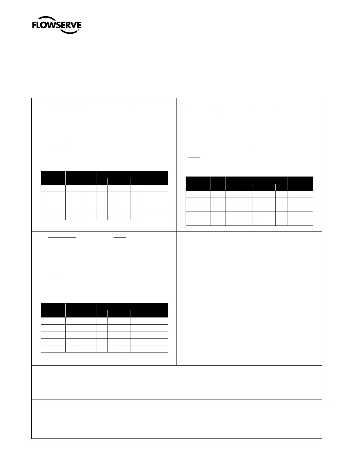
3 HAZARDOUS AREA CERTIFICATIONS
c
DANGER:Certifications listed on the positioner are correct for that positioner. Before using the information on this page, ensure the certifications on the
positioner label match the certifications on this page.
Table 13: Logix 500+ Series Hazardous Locations Information
ATEX North America (cFMus)
IECEx
Notes
• Reference installation drawing # 291780
Warning!
• Limit Switch options -01, -03, -04, -05, -06 are not rated for use in hazardous are.
• Covers must be properly installed in order to maintain environmental ratings.
Special Conditions for Safe Use:
• The equipment must be installed in such a manner as to minimize the risk of impact
or friction with other metal surfaces.
• To avoid possibility of static discharge clean only with a damp Cloth
• For Intrinsically Safe installations the positioner must be connected to suitably rated
intrinsically safe equipment, and must be installed in accordance with applicable
intrinsically safe installation standards.
• Substitution of components may impair Intrinsic Safety.
• Use appropriately rated cable insulation at higher temperatures.
• For type ‘nA’ and Type ‘tb’ installation only air or inert gas may be connected to the
air supply inlet.
• Provisions shall be made externally to provide transient over voltage protection to a
level not to exceed 140% of the peak rated input voltage.
Conditions spéciales pour une utilisation en toute sécurité:
• Le matériel doit être installé de sorte à réduire au minimum le risque de choc ou de frottement avec d’autres surfaces métalliques.
• Pour éviter les risques de décharge d’électricité statique Nettoyez uniquement avec un chiffon humide
• Pour les installations en sécurité intrinsèque, le positionneur doit être connecté à un équipement sécurité intrinsèque convenablement qualifié, et doit être installé conformément
aux normes d’installation sécurité intrinsèque applicables.
Assessed to the following ATEX standards: EN 60079-0:2012, , EN 60079-11:2012, EN 60079-15:2010, EN 60079-26:2007, EN 60079-31:2014, EN60529:1991+A1:2000
Assessed to the following IECEx standards: IEC 60079-0:2011, IEC 60079-11:2011, IEC 60079-15:2010, IEC 60079-31:2013, IEC 60079-26:2006.
Assessed to the following US standards: Class 3600 :2011,Class 3610 :2010, FM 3611, Class 3810 :2005, ANSI/NEMA 250 :2008, ANSI/IEC 60529 :2004, ANSI/ISA 60079-0 :2013
ANSI/ISA 60079-1 :2009, ANSI/ISA 60079-11:2011, ANSI/ISA 60079-15:2012,ANSI/ISA 60079-31:2013.
Assessed to the following CAN standards: CSA C22.2 No.0.4, CSA C22.2 No. 0.5, CSA C22.2 No.60529, CSA C22.2 60079-0, CSA C22.2 60079-1,CSA C22.2 No. 157, CSA C22.2
No.213,CSA No. 60079-11, CSA C22.2 No. 60529.
Intrinsically Safe
FM12ATEX0009X
II 1 G
Ex ia IIC T4/T6 Ga IP66
T4 Tamb = -20˚C ≤ Ta ≤ +85˚C
T6 Tamb = -52˚C ≤ Ta ≤ +45˚C
Type ‘n’
FM15ATEX0002X
II 3 G
Ex nA IIC T4/T6 Gc IP65
T4 Tamb = -20˚C ≤ Ta ≤ +85˚C
T6 Tamb = -52˚C ≤ Ta ≤ +45˚C
Type ‘t’
II 2 D
FM12ATEX0009X
Ex tb IIIC T100˚C Db IP65
Tamb = -52˚C ≤ Ta ≤ +85˚C
Entity
Parameters
4-20
Input
MFC
Limit Switches
Remote Mount
-02 -03 -04 -05
Ui (Vdc)= 30 30 10.6 16 16 16 Vo = 5V
Ii (mA)= 100 100 29.7 25 25 25 Io = 79mA
Pi (mW)= 800 800 79 34 34 34 Po = 129mW
Ci (nF)= 0 0 1 40 60 30 Co = 2uF
Li (µH)= 47 0 1 50 100 100 Lo = 100uH
Entity
Parameters
4-20
Input
MFC
Limit Switches
Remote Mount
-02 -03 -04 -05
Ui (Vdc)= 30 30 10.6 16 16 16 Vo = 5V
Ii (mA)= 100 100 29.7 25 25 25 Io = 79mA
Pi (mW)= 800 800 79 34 34 34 Po = 129mW
Ci (nF)= 0 0 1 40 60 30 Co = 2uF
Li (µH)= 47 0 1 50 100 100 Lo = 100uH
Entity
Parameters
4-20
Input
MFC
Limit Switches
Remote Mount
-02 -03 -04 -05
Ui (Vdc)= 30 30 10.6 16 16 16 Vo = 5V
Ii (mA)= 100 100 29.7 25 25 25 Io = 79mA
Pi (mW)= 800 800 79 34 34 34 Po = 129mW
Ci (nF)= 0 0 1 40 60 30 Co = 2uF
Li (µH)= 47 0 1 50 100 100 Lo = 100uH
Intrinsically Safe
FM12ATEX0009X
II 1 G
Ex ia IIC T4/T6 Ga IP66
T4 Tamb = -20˚C ≤ Ta ≤ +85˚C
T6 Tamb = -52˚C ≤ Ta ≤ +45˚C
Type ‘n’
FM15ATEX0002X
II 3 G
Ex nA IIC T4/T6 Gc IP65
T4 Tamb = -20˚C ≤ Ta ≤ +85˚C
T6 Tamb = -52˚C ≤ Ta ≤ +45˚C
Type ‘t’
II 2 D
FM12ATEX0009X
Ex tb IIIC T100˚C Db IP65
Tamb = -52˚C ≤ Ta ≤ +85˚C
Intrinsically Safe
Class I, Div 1, Groups A,B,C,D
Class I, Zone 0, AExia IIC T4/T6 Ga
Class I, Zone 0, Ex ia IIC T4/T6 Ga
T4 Tamb = -20˚C ≤ Ta ≤ +85˚C
T6 Tamb = -52˚C ≤ Ta ≤ +45˚C
NEMA Type 4X, IP66
Type ‘n’
Class 1, Zone 2, AEx nA IIC T4/T6 Gc
Class 1, Zone 2, Ex nA IIC T4/T6 Gc
T4 Tamb = -20˚C ≤ Ta ≤ +85˚C
T6 Tamb = -52˚C ≤ Ta ≤ +45˚C
NEMA Type 4X, IP65
Type ‘t’
Zone 21, AEx tb IIIC T100˚C Db IP65
Tamb = -52˚C ≤ Ta ≤ +85˚C
Non-Incendive
Class I, Div 2, Groups A,B,C,D,
T4 Tamb = -20˚C ≤ Ta ≤ +85˚C
T6 Tamb = -52˚C ≤ Ta ≤ +45˚C
NEMA Type 4X, IP65