23
Logix
®
520MD+ and 510+ Digital Positioners FCD LGENIM0105-15-AQ – 05/16
flowserve.com
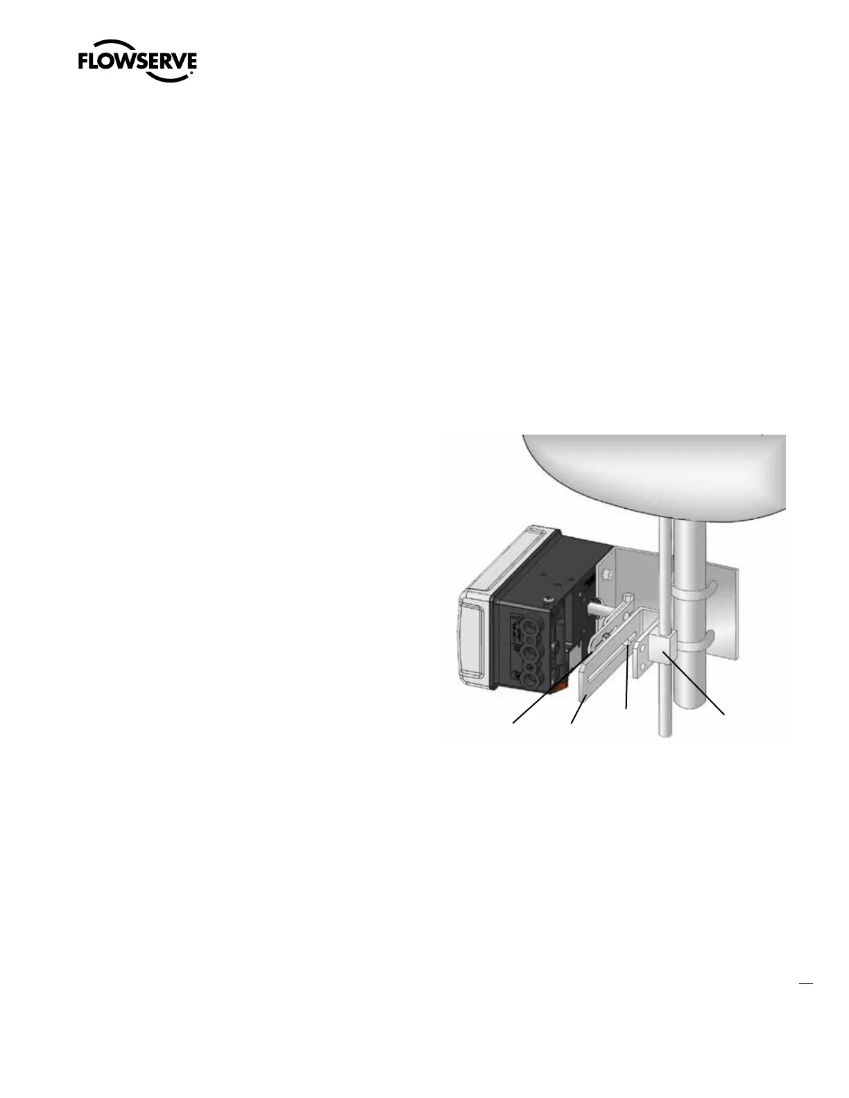
5.6 Mounting to a Linear NAMUR Pneumatic Actuator
The mounting of a rod actuator kit and actuator (according to IEC 534
part 6) is described in the following example. Refer to Figure 19.
1. Mount the follower arm by unscrewing the lock nut for the
follower arm attachment. Place the follower arm on the shaft
at the back of the positioner and fasten it with the lock nut. The
follower pin should point away from the positioner.
2. Attach the stem clamp bracket to the stem clamp and fasten it
with two hexagon socket screws and lock washers.
3. Attach the take-off arm to the stem clamp bracket and fasten it
with a hexagon socket caps crew and a washer.
a
CAUTION: Maximum torque 0,25 Nm (0,18 ft-lbs).
4. To mount the positioner, adjust the actuator to mid-stroke.
5. Pre-assemble the mounting bracket on the left actuator leg and
hand-tighten the two U-bolts, nuts and lock-washers.
6. Attach the positioner to the pre-assembled mounting bracket and
fasten it with two hexagon screws and two lock washers. Check
that the follower pin is inserted in the slot of the take-off arm and
the follower arm is positioned parallel to the take-off arm.
7. Tighten all screws and nuts.
NOTE: The feedback shaft has a clutch mechanism that allows
for over-rotation of the shaft for easy adjustments.
NOTE: A slight unsymmetrical mounting increases the linearity
deviation but does not affect the performance of the device.
NOTE: Depending on the actuator size and stroke it may be
necessary to flip the take-off arm (Figure 3) by 180° and attach it
to the opposite side of the stem clamp bracket.
8. Connect regulated air supply to appropriate port in manifold. See
section 6 TUBING.
9. Connect the power to the 4-20 mA terminals. See section 7
ELECTRICAL CONNECTIONS.
10. Remove main cover and locate DIP switches and QUICK-CAL/
ACCEPT button.
11. Refer to sticker on main board cover and set DIP switches
accordingly. See section 8 STARTUP.
12. Press the QUICK-CAL/ACCEPT button for three to four seconds
or until the positioner begins to move. The positioner will now
perform a stroke calibration.
13. If the calibration was successful the green LED will blink GGGG
or GGGY and the valve will be in control mode.
14. If calibration fails, as indicated by a RGGY blink code, retry the
calibration. If it still fails, remove power from the positioner,
disconnect the air, and remove the positioner from the actuator.
Rotate the feedback shaft so that the full free travel of the feed-
back shaft is in the range of the actuator movement. Optionally,
continue to attempt the calibration. Each calibration attempt
adjusts the acceptable limits and it should pass eventually.
a
CAUTION: Remember to remove the air supply before re-adjusting
take-off arm.
Follower
Arm
Take Off
Arm
Follower
Pin
Stem Clamp
Figure 19: Mounting to a Linear Actuator