Logix
®
520MD+ and 510+ Digital Positioners FCD LGENIM0105-15-AQ – 05/16
32
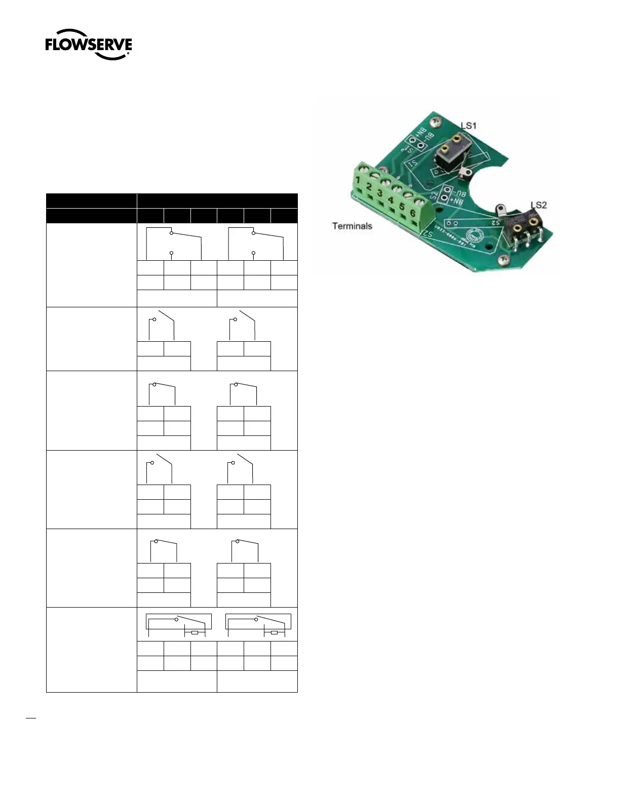
7.5 Limit Switches
Limit switches provide an independent verification of the position
of the feedback shaft. Wire the limit switches according to Table 15:
Limit Switch Connections. For more information, see Table 7: Limit
Switch Specifications on page 11. See Figure 34.
Table 15: Limit Switch Connections
Terminal (See Figure 34)
Switch 1 2 3 4 5 6
Mechanical
Cherry DG 13-B2RA
1 & 4 NC
NC NO C NC NO C
+ + - + + -
LS1 LS2
Reed
Hamlin 59165-1-S-00-C
NO
+ - + -
LS1 LS2
Inductive Sensor
P&F NJ2-V3-N
NAMUR NC
BN BU BN BU
+ - + -
LS1 LS2
Inductive Proximity
P&F SJ2-S1N
NAMUR NO
BN BU BN BU
+ - + -
LS1 LS2
Inductive Proximity
P&F SJ2-SN
NAMUR NC
BN BU BN BU
+ - + -
LS1 LS2
Inductive Sensor
P&F NBB2-V3-E2
PNP NO
General Purpose Only
BN BU BK BN BU BK
Vcc+ - SW+ Vcc+ - SW+
LS1 LS2
Figure 34: Limit Switch Board