Logix
®
520MD+ and 510+ Digital Positioners FCD LGENIM0105-15-AQ – 05/16
46
Table 19: Characteristic Curve Data
Final Command
Command
Input
Characterization
DIP set to “Linear”
Characterization DIP set to “Other”
Linear MaxFlo Linear MaxFlo =% Valdisk Linear Valdisk =%
Shear-Stream
Linear
Shearstream=%
Custom
(Default)
(Linear=%)
0.0 0.00 0.00 0.00 0.00 0.00 0.00 0.00 0.00
5.0 5.00 6.50 1.00 13.00 4.00 25.00 8.00 0.62
10.0 10.00 11.60 2.00 20.00 6.00 35.00 14.00 1.35
15.0 15.00 16.20 3.00 26.25 7.80 44.00 17.00 2.22
20.0 20.00 20.50 4.40 32.10 9.30 50.20 21.00 3.25
25.0 25.00 24.60 5.80 37.50 11.50 55.50 24.00 4.47
30.0 30.00 28.50 7.40 42.60 14.00 60.20 27.50 5.91
35.0 35.00 32.40 9.30 47.40 16.50 64.30 31.50 7.63
40.0 40.00 36.20 11.20 51.80 19.30 68.00 35.50 9.66
45.0 45.00 40.00 13.50 56.00 22.50 71.50 39.50 12.07
50.0 50.00 43.80 16.10 60.00 26.00 74.70 43.90 14.92
55.0 55.00 47.60 19.10 63.60 30.00 77.70 48.10 18.31
60.0 60.00 51.50 22.40 67.20 34.70 80.50 52.80 22.32
65.0 65.00 55.50 26.20 70.60 39.60 83.20 57.40 27.08
70.0 70.00 59.50 30.60 73.90 45.10 85.90 62.40 32.71
75.0 75.00 63.80 35.70 77.20 51.30 88.40 67.50 39.40
80.0 80.00 68.20 41.70 81.30 57.80 90.80 72.90 47.32
85.0 85.00 73.00 48.90 84.00 64.80 93.20 78.60 56.71
90.0 90.00 78.40 57.70 87.80 72.50 95.50 84.70 67.84
95.0 95.00 85.00 69.20 92.10 81.30 97.80 91.20 81.03
100.0 100.00 100.00 100.00 100.00 100.00 100.00 100.00 100.00
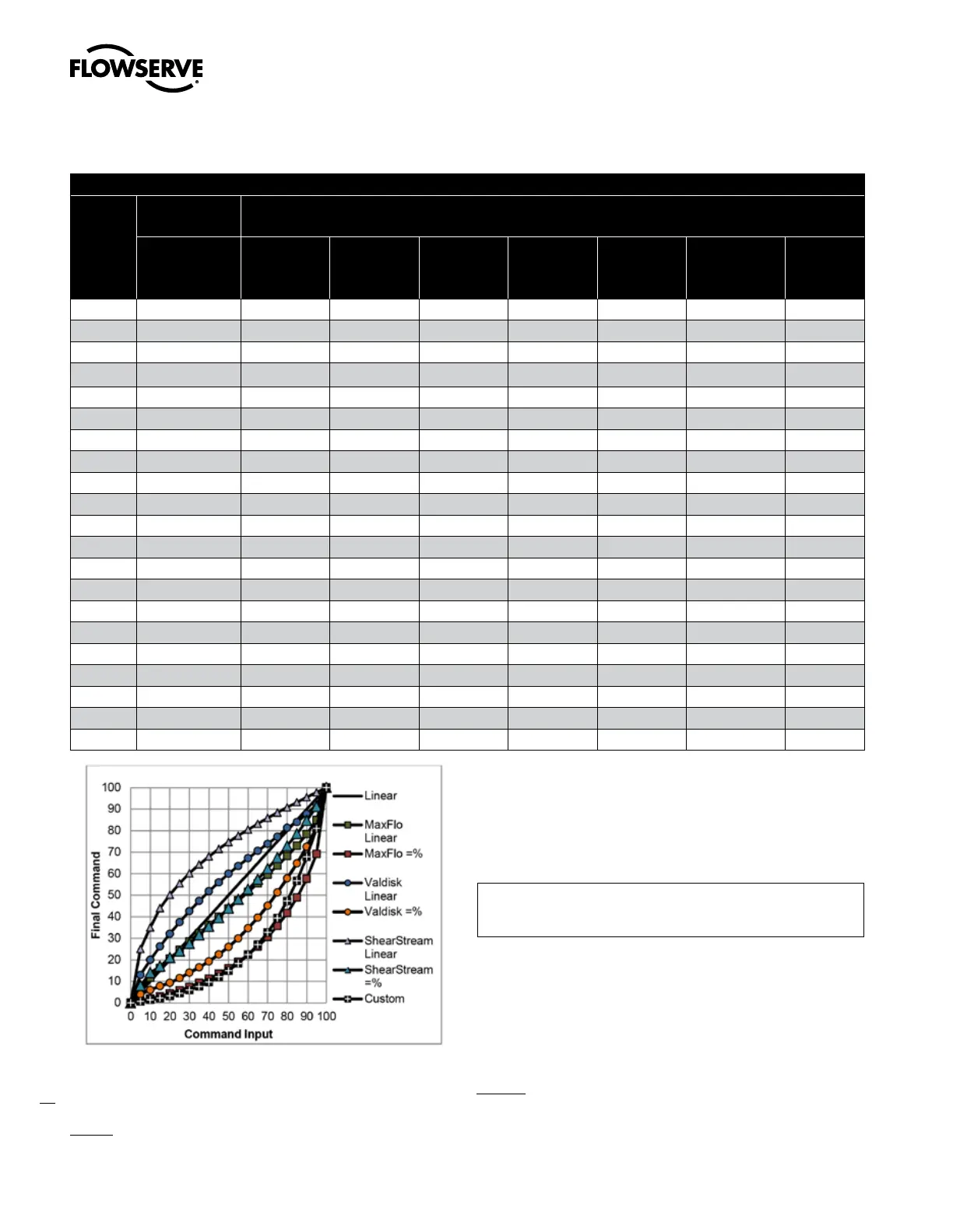
Figure 39: Characterization Curves
Select the appropriate curve as required by the process design.
Custom - Select Custom for a standard 30:1 linear equal percent
rangeability curve. The curve may be customized point-by point. To
modify the Custom curve, use the ValveSight DTM.
a
CAUTION: Changing the characterization curve may cause the
valve to move suddenly. Notify proper personnel that the valve
may stroke and if required, make sure the valve is properly
isolated before proceeding.
10.3.7 Configuration (Pressure Control)
.Configuration
.Pressure Control
.Window
The Configuration (Pressure Control) menu allows the user to change
the size of the pressure control window. This window becomes active
when the Valve Stability Switch is set to “Hi”. The Valve Stability
Switch optimizes the response for valves and actuators with high
friction levels. When set to “Hi”, it slightly slows the response and will
normally stop limit cycling that can occur on high friction valves.
Window - When the position of the valve gets within the pressure
control window, the positioning algorithm will change to pressure
control. This means the pressures will be held constant (locked),
improving the stability of the valve position