Logix
®
520MD+ and 510+ Digital Positioners FCD LGENIM0105-15-AQ – 05/16
30
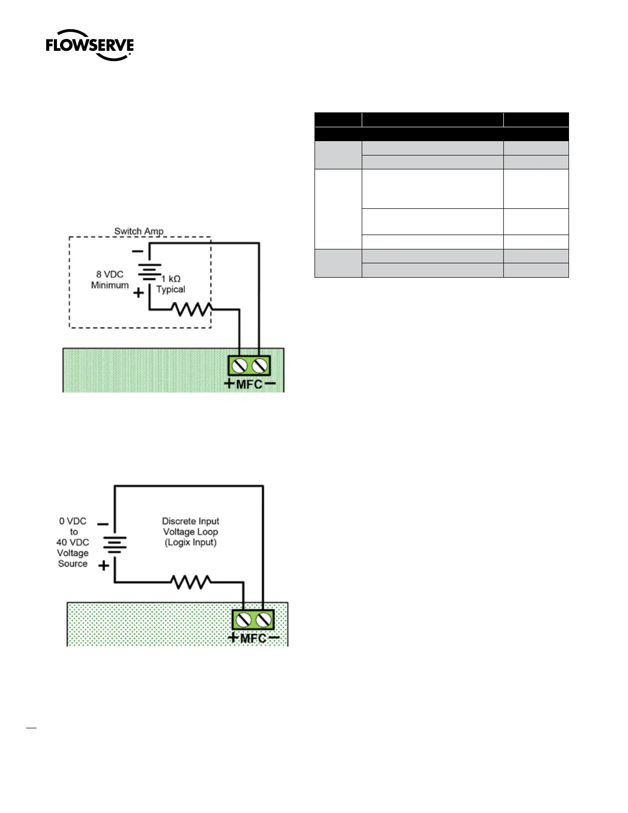
7.3.2 Discrete Output
For DO function, wire the MFC in series with a 8 to 40 VDC power
supply, including a method to determine the current such as a resis-
tor. Or use a NAMUR switch amplifier made for this purpose. In DO
configuration, the card is a NAMUR switch.
When configured as a DO, current will remain high until the user-de-
fined condition (an alarm) is active, and then drop low when tripped.
See Figure 29.
Figure 29: MFC Discrete Output Circuit
7.3.3 Discrete Input
For the DI function, wire the MFC in series with a 0 to 40 VDC power
supply. Keep the voltage low under normal circumstances. Raise the
voltage to create a tripped input state. See Figure 30.
Figure 30: MFC Discrete Input Circuit
Table 14: Auxiliary Card Status
Card Condition Status Indication
Multi-Function Card
MFC (AO)
Monitoring Position (typical 4-20mA ) Output (mA)
Less than 8 V on AO terminals. No Loop Power
MFC (DO)
High output > 2.1 mA
(520MD+ typically 3 mA)
(510+ typically 7 mA)
1 - Nominal
Low 1.2 mA > output > 0.1 mA
(typically 0.5 mA)
0 - Tripped
Less than 0.1 mA No Loop Power
MFC (DI)
Low (input < 2.5 VDC) 1 - Nominal
High (input > 8.0 VDC) 0 - Tripped