EasyManuals Logo

Flowserve Logix 520MD+ User Manual

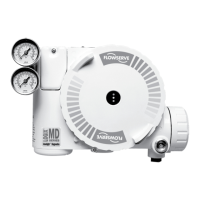
Flowserve Logix 520MD+
84 pages
To Next Page IconTo Next Page
To Previous Page IconTo Previous Page
Page #9 background imageLoading...
Page #9 background image
9
Logix
®
520MD+ and 510+ Digital Positioners FCD LGENIM0105-15-AQ – 05/16
flowserve.com
1 Piezo Assembly
2 Block
3 Spool
4 Regulator Assembly
5 Piezo Cable
6 Hall Sensor Cable
7 Auxiliary Card
8 Main Board
9 4-20 mA Input
10 Hall Sensor Assembly
11 Exhaust
12 Port B
13 Supply Pressure
14 Pressure Sensor Board
15 Supply In
16 Pressure Sensor Cable
17 Feedback Cable
18 Exhaust
19 Port A
20 Feedback Potentiometer
21 Actuator Housing
22 Spring
23 Piston
24 Stem
25 Yoke
26 Take-Off Arm
Figure 3: Logix 500+ Digital Positioner Schematic (Double Acting Relay - Air To Open)
1
2
3
4
5
6
7
8
9
10
21
16
17
19
20
26
25
24
23
22
18
15
13
14
12
11

Table of Contents

Questions and Answers:

Question and Answer IconNeed help?

Do you have a question about the Flowserve Logix 520MD+ and is the answer not in the manual?

Flowserve Logix 520MD+ Specifications

General IconGeneral
BrandFlowserve
ModelLogix 520MD+
CategoryValve Positioners
LanguageEnglish

Related product manuals