Do you have a question about the Flowserve Logix 3200MD and is the answer not in the manual?
Defines safety terms (DANGER, WARNING, CAUTION, NOTE) and general practices.
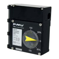
Introduces the Logix 3200MD positioner and the manual's coverage.
Details unpacking procedures, checking contents, and pre-installation checks.
Provides recommendations for safely storing control valve packages.
Lists electrical, environmental, physical, and performance specifications for the positioner.
Explains the 4-20 mA input, HART protocol, and software characterization.
Provides an example of the positioner's control function and inner-loop offset.
Lists certifications, approvals, parameters, temp codes, and enclosure ratings.
Step-by-step guide for mounting the positioner onto Valtek linear Mark One valves.
Lists required tools and outlines the procedure for mounting to standard Valtek rotary valves.
Details the procedure for optional rotary mounting using a four-bar linkage.
Explains tubing requirements and recommendations for connecting the positioner to the actuator.
Describes tubing for actuators and guidelines for electrical connections, grounding, and conduit.
Details wiring for the 4-20 mA input, polarity, and minimum current.
Explains the use of the green grounding screw for earth ground reference.
Explains output compliance voltage and how to calculate loop support.
Discusses cable requirements for HART protocol communication on the 4-20 mA signal.
Advises on selecting intrinsically safe barriers compatible with HART communication.
Describes the local interface, DIP switches, and initial settings for configuration.
Explains DIP switches for Air Action, Signal at Closed, and Position Characterization.
Presents data for default custom characterization curves (Linear, Equal %, Custom).
Explains how the Auto Tune feature works with selectable gain settings.
Describes how the stability switch optimizes response for low or high friction valves.
Explains the function of the Cal DIP switch for Auto or Jog calibration modes.
Details how to start and cancel the QUICK-CAL process for positioner calibration.
Explains how to use jog buttons for local manual control of valve position.
Describes how to reset the positioner to factory defaults and the consequences.
Explains how to reset the command source to analog mode.
Details how to check the positioner's embedded code version number.
Explains how blink codes indicate the positioner's operational status or alarms.
Lists and explains various blink codes indicating positioner status and potential issues.
Introduces ValveSight software and HART 375 communicator for configuration and diagnostics.
Describes the driver module and its function.
Provides tools and steps for replacing the driver module assembly.
Explains the regulator's role and provides steps for its replacement.
Lists required tools and the procedure to check or set internal regulator pressure.
Describes the spool valve's function and provides steps for its replacement.
Details steps to replace the filter element in the spool valve cover.
Explains the sensor's role and provides steps for its replacement.
Describes the main PCB's role and provides steps for its replacement.
Explains the sensor board's function and provides steps for its removal.
Details steps for installing the pressure sensor board.
Provides tools and steps for replacing the customer interface board.
Explains the vented design for routing exhausted natural gas and its limitations.
Describes the HART modem for computer communication and its power requirements.
Lists features and steps for replacing the analog feedback signal option.
Lists all parts with corresponding item numbers for reference.
Lists spare parts kits for driver module, spool valve, and pressure regulator components.
Lists spare parts kits for feedback shaft, main PCB, and customer interface board.
Lists spare parts kits for analog output board and available HART modem options.
Provides part numbers for mounting kits for Valtek linear and Valtork rotary valves.
Lists OEM mounting kits for various actuator brands and models.
Specifies part numbers for NAMUR accessory mounting kits based on bracket and bolt options.
Addresses common questions regarding power, communication, MPC, diagnostics, and upgrades.
Provides a guide for selecting options like protocol, diagnostics, material, and certifications.
Addresses issues with no LED indication or erratic communication.
Solves problems with no response to commands or incorrect valve position readings.
Addresses issues of sticking or hunting behavior in the positioner's operation.
| Brand | Flowserve |
|---|---|
| Model | Logix 3200MD |
| Category | Valve Positioners |
| Language | English |
