User instructions - Digital Positioner 3200MD LGENIM0059-01 10/08
9
7. Position the take-off arm mounting slot against the stem clamp
mounting pad. Apply Loctite 222 to the take-off arm bolting and
insert through washers into stem clamp. Leave bolts loose.
8. Slide the appropriate pin slot of the take-off arm, based on
stroke length, over the follower arm pin. The appropriate stroke
lengths are stamped by each pin slot.
9. Center the take-off arm on the rolling sleeve of the follower pin.
10. Align the take-off arm with the top plane of the stem clamp and
tighten bolting. Torque to 120 in-lb.
NOTE: If mounted properly, the follower arm should be horizon-
tal when the valve is at 50% stroke and should move approxi-
mately ±30° from horizontal over the full stroke of the valve. If
mounted incorrectly, a stroke calibration error will occur and the
indicator lights will blink a RGGY code indicating the position
sensor has gone out of range on one end of travel. Reposition
the feedback linkage or rotate the position sensor to correct the
error.
5.2 Mounting to Standard
Valtek Rotary Valves (See Figure 4)
The standard rotary mounting applies to Valtek valve/actuator as-
semblies that do not have mounted volume tanks or handwheels.
The standard mounting uses a linkage directly coupled to the valve
shaft. This linkage has been designed to allow for minimal misalign-
ment between the positioner and the actuator. The tools required for
the following procedure are:
•
5
⁄32" Allen wrench
• "open-endwrench
•
7
⁄16" open-end wrench
•
3
⁄8" socket with extension
•
3
⁄16" nutdriver
1. Fasten the spline lever adapter to the splined lever using two 6 x
½" self-tapping screws.
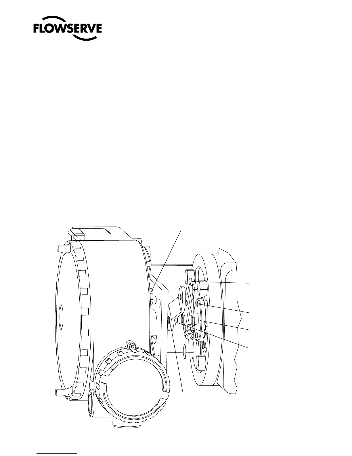
Figure 4: Standard Rotary Mounting
Positioner Bolts ¼-20 (4)*
* Located in appropriate
hole pattern as indicated on
bracket. (25, 50, 100/200)
Take-off Arm, Rotary
Lock Washer (2)
10-32 Bolt
10-32 Nut
Self-tapping Screws (2)
Spline Lever Adapter
10-32 Nut
Lock Washer
Follower Arm
Logix 3200MD
Digital Positioner
Bracket Bolts
-18 (2, not shown)
5
/16