User instructions - Digital Positioner 3200MD LGENIM0059-01 10/08
23
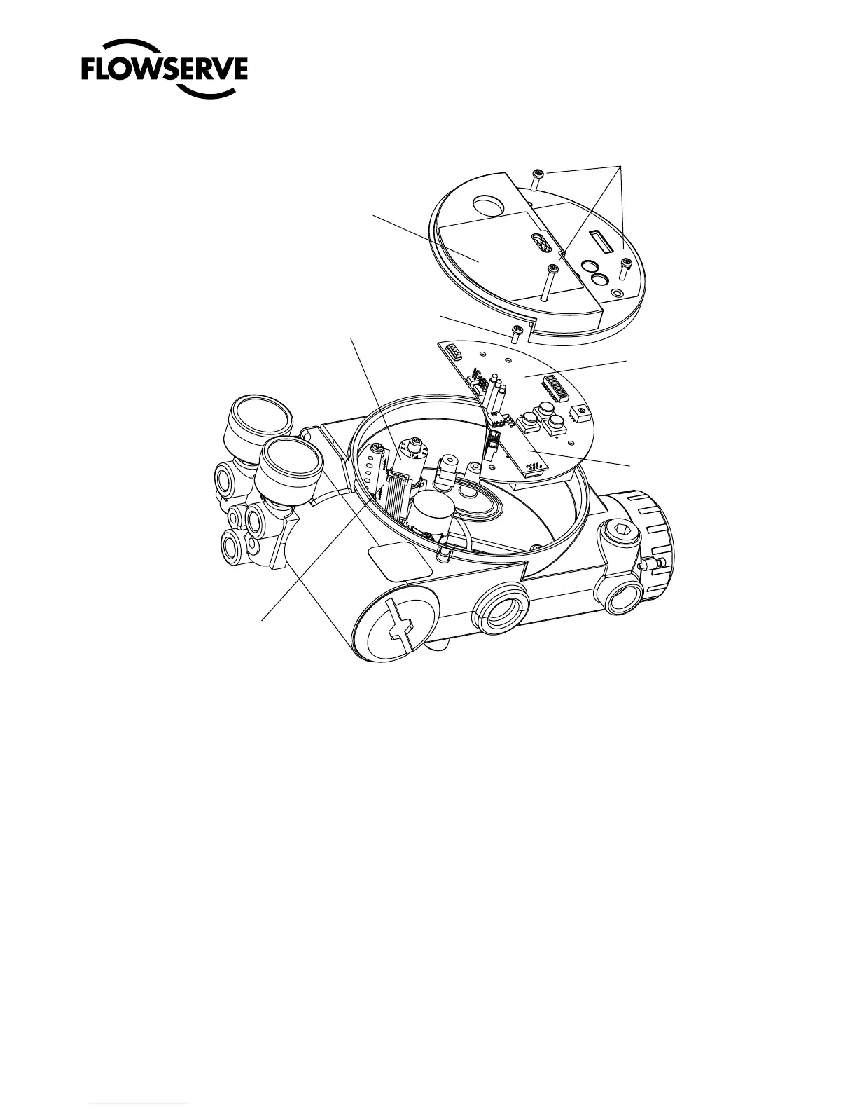
Figure 15: Main PCB Assembly
.BJO1$#
"OBMPH0VUQVU#PBSE
1SFTTVSF4FOTPS#PBSE
3FHVMBUPS
1MBTUJD
#PBSE
$PWFS
.BJO1$#
3FUBJOJOH
4DSFXT
1MBTUJD$PWFS
3FUBJOJOH4DSFXT
block toward the driver module until the two retaining holes line
up with the threaded holes in the base.
27. Install two spool-valve screws and tighten securely with a Phil-
lips screwdriver (see Figure 13).
28. Slide the spool valve cover assembly over the spool valve until
the tang engages into the housing slot. Install spool valve cover
screw and tighten securely (see Figure 12).
29. Install the plastic board cover. Insert the three retaining screw
through the plastic cover into the threaded boss and tighten
evenly, using a Phillips screwdriver. Do not overtighten (see
Figure 15).
30. Reconnect power and air supply to the positioner and perform a
stroke calibration.
31. Reinstall all covers.
8.2 Regulator
The regulator reduces the pressure of the incoming supply air to a
level that the driver module can use.
Replacing Regulator
To replace the regulator, refer to Figures 11 and 15 and proceed as
outlined below. The following tools are required:
• Phillipsscrewdriver
• "nutdriver
c
WARNING: Observe precautions for handling electrostati-
cally sensitive devices.
1. Make sure valve is bypassed or in a safe condition.
2. Disconnect the power and air supply to the unit.
3. Remove the main cover.
4. Remove the plastic board cover by removing the three retaining
screws (see Figure 15).