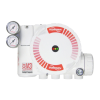
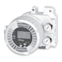
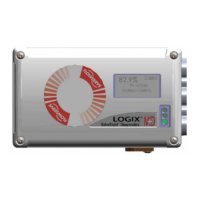
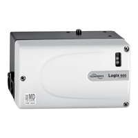
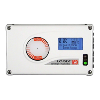
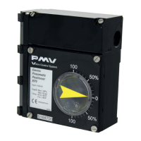
User instructions - Digital Positioner 3200MD LGENIM0059-01 10/08
2
Contents
1 Terms Concerning Safety 3
2 General Information 3
3 Unpacking and Storage 3
3.1 Unpacking 3
3.2 Storage 3
3.3 Pre-installation Inspection 3
4 Logix 3200MD Positioner Overview 4
4.1 Specifications 4
4.2 Positioner Operation 6
4.3 Detailed Sequence of Positioner Operations 7
5 Mounting and Installation 8
5.1 Mounting to Valtek Linear Mark One Valves 8
5.2 Mounting to Standard Valtek Rotary Valves 9
5.3 Optional Valtek Rotary Mounting Procedure 11
5.4 Tubing Positioner to Actuator 11
6 Wiring and Grounding Guidelines 12
6.1 4-20 mA Command Input Wiring 13
6.2 Grounding Screw 13
6.3 Compliance Voltage 13
6.4 Cable Requirements 13
6.5 Intrinsically Safe Barriers 14
7 Startup 14
7.1 Logix 3200MD Local Interface 14
7.2 Initial DIP Switch Settings Operation 14
7.3 Operation of Configuration DIP Switch Settings 15
7.4 Setup of the Cal Dip-Switch for the Quick Calibration
operating mode. 16
7.5 QUICK-CAL Operation 16
7.6 Local control of valve position 17
7.7 Factory Reset 17
7.8 Command Reset 17
7.9 Version number checking 17
7.10 Logix 3200MD Status Condition 17
7.11 ValveSight Configuration and Diagnostic Software and
HART 375 Handheld Communicator 18
8 Maintenance and Repair 21
8.1 Driver Module Assembly 21
8.2 Regulator 23
8.3 Checking or Setting Internal Regulator Pressure 24
8.4 Spool Valve 25
8.5 Spool Valve Cover 25
8.6 Stem Position Sensor 26
8.7 Main PCB Assembly 27
8.8 Pressure Sensor Board 27
8.9 Customer Interface Board 28
9 Optional Hardware 29
9.1 Vented Design 29
9.2 HART Modem 30
9.3 4-20 mA Analog Output Board 30
10 Parts List 32
11 Logix 3200MD Spare Parts Kits 34
12 Logix 3200MD Mounting Kits 35
12.1 Valtek Mounting Kits 35
12.2 Logix O.E.M. Mounting Kits 36
12.3 NAMUR Accessory Mounting Kit Part Numbers 36
13 Frequently Asked Questions 37
14 How to Order 38
15 Troubleshooting 39
 Loading...
