User instructions - Digital Positioner 3200MD LGENIM0059-01 10/08
30
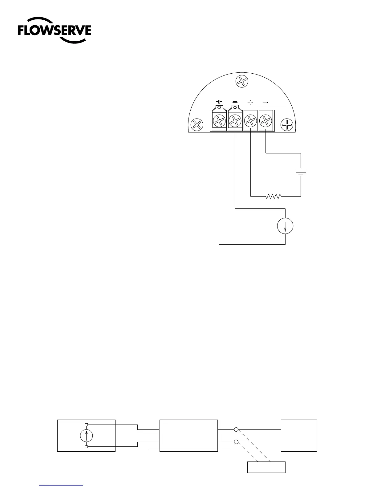
9.3 4-20 mA Analog Output Board
The Logix 3200MD digital positioner can be supplied to provide an
analog feedback signal of the stem position. This option can also be
retrofitted in the field. The 4-20 mA analog output board is wired in
series with a 12.5 to 40 VDC power supply (see Figure 23). This po-
sition feedback option has the following features and specifications:
• Doesnotinterferewithpositioneroperation.
• CalibrationoftheanalogoutputsignalisperformedusingaHART
375 Handheld Communicator or configuration software such as
ValveSight.
• Outputfollowsactualpositionofvalve,includingallfailuremodes
of positioner except loss of power. An output of ≤3.15 mA is trans-
mitted with loss of power to the positioner.
• ImmunetoRFI/EMIdisturbances.
• Availableforexplosion-proofandsafeapplications(CSA,FM).
Replacing the 4-20 mA Analog Output Board
To replace the 4-20 mA analog output board, refer to Figures 11,
15 and 25 and proceed as outlined below. The following tools are
required:
• Phillipsscrewdriver
c
WARNING: Observe precautions for handling electrostati-
cally sensitive devices.
Figure 23: Analog Output Board Power
)"35
N"
"/"-0(
*/165 065165
1PTJUJPO'FFECBDL
$VSSFOU-PPQ
-PHJY0VUQVU
1PTJUJPO$PNNBOE
$VSSFOU-PPQ
-PHJY*OQVU
$"65*0/*TPMBUFE1PXFS4PVSDFT3FRVJSFE
7%$
UP7%$
1PXFS
4VQQMZ
UPN"
$VSSFOU4PVSDF
o
o
a
CAUTION: Isolated power sources required.
1. Make sure the valve is bypassed or in a safe condition.
2. Disconnect the power and air supply to the unit.
3. Remove the main cover.
4. Remove the plastic board cover by removing the three retaining
screws (see Figure 15).
5. Disconnect the two wire connection from the side of the
4-20 mA analog output board.
6. Gently lift the 4-20 mA analog output board off the main PCB
assembly.
Figure 22: HART VHF Filter Schematic
$
%
'
&
() "#
%$4
-0(*9
)"35$POOFDUJPO
'*-5&3
%SBJO8JSF
N"
$VSSFOU4PVSDF
-PHJY
99*2