®
User instructions - Digital Positioner 3200MD LGENIM0059-01 10/08
39
*Contact factory before specifying this option
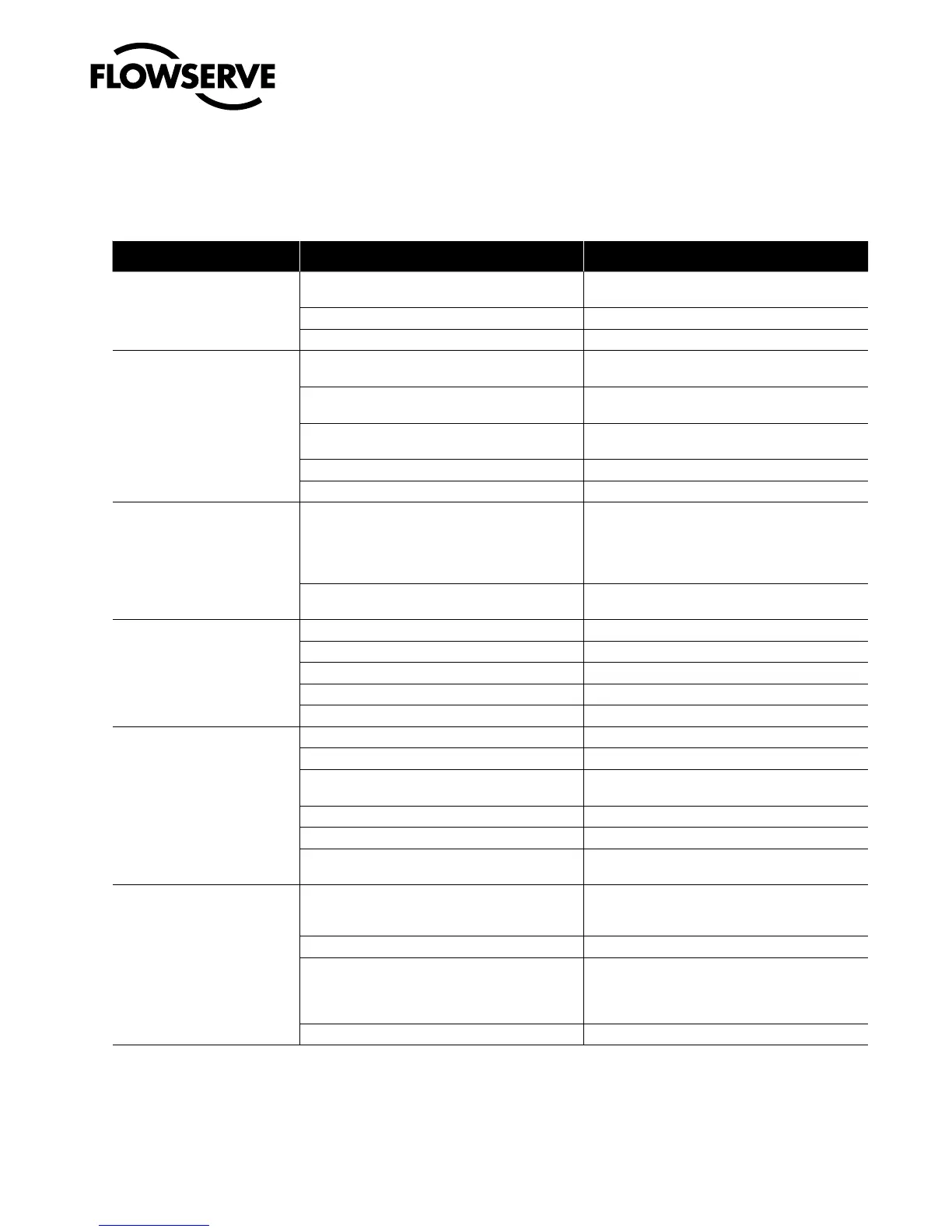
15 Troubleshooting
Failure Probable Cause Corrective Action
No LED is blinking
Current source below 3.6 mA without AO card or 3.7 mA
with AO card
Verify current source is outputting at least 3.6 mA with
AO card or 3.7 mA with AO card
Incorrect wiring polarity Check wiring for correct polarity
Voltage of current source is not high enough Verify that current source can supply at least 10 V
Erratic communications
Current source bandwidth not limited to 25 Hz
Maximum allowable current source rate of change is
924 mA per second
Maximum cable length or cable impedance exceeded
Check cable conduction size, length and capacitance.
Refer to Section 6.4, “Cable Requirements”
HART modem connected to PC RS-232 port not receiv-
ing enough power
Verify laptop battery is not low
Interference with I.S. barrier Must use HART-compatible I.S. barrier
Current Source stripping (filtering) HART signal. Use the HART filter (VHF) available from Flowserve
Unit does not respond to analog
commands
Unit is in digital command mode
Switch to analog command mode by doing a Command
Source Reset from the local interface or with a handheld
communicator or ValveSight (please refer to Section 7.9,
“Command Source Reset,” or the quick start guide for
detailed instructions).
Error occurred during calibration
Check blink codes on positioner and correct
calibration error. Recalibrate
Valve position reading is not
what is expected
Positioner tubing backwards Re-tube the actuator
Stem position sensor mounting is off 180° Remount position sensor
Stroke not calibrated Perform QUICK-CAL
Tight shutoff (M.P.C)* is active Verify settings using PC or handheld software
Customer characterization or soft stops active Verify customer characterization and soft stops
Position is driven fully open or
closed and will not respond to
command
Stroke not calibrated Check DIP switch settings and calibrate valve stroke
Inner-loop hall sensor not connected Verify hardware connections
Wrong air action entered in software
Check ATO (Air-to-open) and ATC
(Air-to-close) settings. Recalibrate
Actuator tubing backward Verify ATO/ATC actuator tubing
Electro-pneumatic converter malfunctioning Replace electro-pneumatic converter
Control parameter inner-loop offset is too high/low
Adjust inner-loop offset and see if proper control
resumes
Sticking or hunting operation of
the positioner
Contamination of the driver module
Check air supply for proper filtering and meeting ISA
specifications ISA-7.0.01. Check the spool valve for
contamination
Control tuning parameters not correct Adjust gain settings using local gain switch
Packing friction high
Enable the stability DIP switch on the local interface
and recalibrate. If problem persists, enable pressure
control with handheld communicator or ValveSight and
recalibrate
Corroded or dirty spool valve Disassemble and clean spool valve
*M.P.C.: Minimum position cutoff