User instructions - Digital Positioner 3200MD LGENIM0059-01 10/08
21
7.11 ValveSight Configuration and
Diagnostic Software and HART 375
Handheld Communicator
Flowserve Corporation has written custom configuration and
diagnostic software for the Logix 3200MD digital positioner called
ValveSight. This software is available from a Flowserve representa-
tive.
The Logix 3200MD digital positioner supports and is supported by
the HART 375 Handheld Communicator. The Device Description
(DD) files and the manual listed below can be obtained from the
HART Communication Foundation or from your Flowserve represen-
tative. For more information please see the following guide:
• ProductManualfortheHARTCommunicator.
Diagnostic features such as the datalog, signature tests, and ramp
tests are performed using the ValveSight software. Certain calibra-
tion features such as loop calibration, analog output calibration, and
actuator pressure sensor calibrations are performed using the HART
375 Handheld Communicator or using diagnostic software such as
ValveSight.
8 Maintenance and Repair
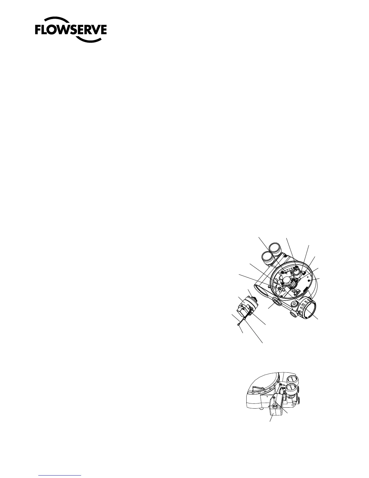
8.1 Driver Module Assembly
The driver module assembly moves the spool valve by means
of a differential pressure across its diaphragm. Air is routed to
the driver module from the regulator through a flexible hose. A
barbed fitting connects the flexible hose to the driver module
assembly. Wires from the driver module assembly connect the
hall effect sensor and the piezo valve modulator to the main PCB
assembly.
Driver Module Assembly Replacement
To replace the driver module assembly, refer to Figures 11-15 and 25
and proceed as outlined below. The following tools are required:
• Flatplateorbarabout
1
⁄8" thick
• Phillipsscrewdriver
• "nutdriver
c
WARNING: Observe precautions for handling electrostati-
cally sensitive devices.
1.
Make sure the valve is bypassed or in a safe condition.
2. Disconnect the power and air supply to the unit.
3. Remove the driver module cover (Figure 14), using a flat bar or
plate in the slot to turn the cover.
4. Remove the spool valve cover by removing the screw and slid-
ing the cover assembly backwards until the tab is clear of the
slot (Figure 12). The sheet metal cap, hydrophobic filter, and
O-ring should be removed with the spool valve cover. It is not
necessary to take these parts out of the spool valve cover.
5. Being careful not to lose the nylon washer, remove the Phillips-
head screw that attaches the driver module to the main housing
(Figure 13).
c
WARNING: Spool (extending from the driver module
assembly) is easily damaged. Use extreme caution when
handling spool and spool valve block. Do not handle the
spool by the machined portions of spool. The toler-
ances between the block and spool are extremely tight.
Contamination in the block or on the spool may cause
the spool to hang.
1SFTTVSF4FOTPS#PBSE
)BMM4FOTPS
$POOFDUJPO
1SFTTVSF
.PEVMBUPS
$POOFDUJPO
0SJOH
%SJWFS.PEVMF
"TTFNCMZ
"OBMPH
0VUQVU
#PBSE
$POOFDUJPO
"OBMPH
0VUQVU#PBSE
*OTUBMM#BSCFE'JUUJOHBGUFS
%SJWFS.PEVMFJTJOIPVTJOH
)BMM4FOTPS$POOFDUPS
1SFTTVSF.PEVMBUPS$POOFDUPS
1PTJUJPOXJSFT
UPUIFSFBS
PG.PEVMBUPS
3FHVMBUPS
1SFTTVSF4FOTPS
#PBSE$POOFDUJPO
6TFS*OUFSGBDF
#PBSE$POOFDUJPO
4UFN1PTJUJPO
4FOTPS
$POOFDUJPO
.BJO1$#
3FUBJOJOH
4DSFX
Figure 11: Driver Module Assembly
Figure 12: Spool Valve Cover Assembly