EasyManua.ls Logo

Flowserve Logix 500 Series User Manual

Flowserve Logix 500 Series
20 pages
To Next Page IconTo Next Page
Page #1 background imageLoading...
Page #1 background image
51-1
Flowserve Corporation, Valtek Control Products, Tel. USA 801 489 8611
GENERAL INFORMATION
The following instructions are designed to assist in
unpacking, installing and performing maintenance as
required on Logix™ 500 Digital Positioners. Series 500
is the term used for all the positioners within the family;
however, specific numbers indicate features specific to
a model: Logix 520 indicates that the positioner uses
HART
®
protocol. Product users and maintenance per-
sonnel should thoroughly review this bulletin prior to
installing, operating, or performing any maintenance on
the valve.
Separate Valtek Flow Control Products Installation,
Operation, Maintenance instructions cover the valve
(such as IOM 1 or IOM 27) and actuator (such as IOM
2 or IOM 31) portions of the system and other acces-
sories. Refer to the appropriate instructions when this
information is needed.
To avoid possible injury to personnel or damage
to valve parts, users must strictly adhere to
WARNING and CAUTION notes. Modifying this
product, substituting non-factory or inferior
parts, or using maintenance procedures other
than outlined could drastically affect perfor-
mance and be hazardous to personnel and equip-
ment, and may void existing warranties.
WARNING: This product has electrical conduit
connections in either thread sizes 0.5-inch NPT or
M20 which appear identical but are not
interchangeable. Forcing dissimilar threads
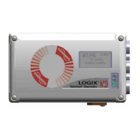
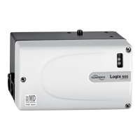
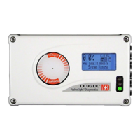
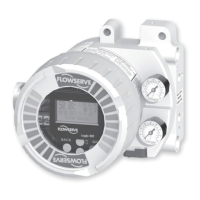
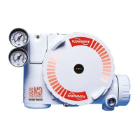
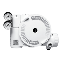
Logix 500 Digital Positioner
Valtek Part No. ?????
together will damage equipment, cause personal
injury and void hazardous location certifications.
Conduit fittings must match equipment housing
threads before installation. If threads do not match,
obtain suitable adapters or contact a Flowserve
office.
WARNING: Standard industry safety practices
must be adhered to when working on this or any
other process control product. Specifically,
personal protective and lifting devices must be
used as warranted.
Unpacking
1. While unpacking the Logix 500 positioner, check
the packing list against the materials received. Lists
describing the system and accessories are included
in each shipping container.
WARNING: When lifting a valve/actuator
assembly with lifting straps, be aware the
center of gravity may be above the lifting
point. Therefore, support must be given to
prevent the valve/actuator from rotating.
Failure to do so can cause serious injury to
personnel or damage to nearby equipment.
2. In the event of shipping damage, contact the ship-
per immediately.
3. Should any problem arise, contact a Flowserve
Flow Control Division representative.

Questions and Answers:

Flowserve Logix 500 Series Specifications

General IconGeneral
Input Signal4-20 mA
Power Supply24 VDC
Communication ProtocolHART
Operating Temperature-40°C to 85°C (-40°F to 185°F)
Protection RatingIP66/NEMA 4X
EnclosureAluminum, Stainless Steel
Supply Pressure2.4 to 7 bar (35 to 100 psig)
Ambient Temperature Range-40°C to 85°C (-40°F to 185°F)

Summary

General Information and Safety Precautions

Electrical Conduit Connection Warning

Warns about interchangeable conduit threads and potential damage or injury.

Unpacking and Shipping Damage Handling

Details steps for checking received materials and handling shipping damage.

Logix 500 Overview and Specifications

Product Overview

Describes the Logix 500 as a 4-20 mA digital valve positioner with HART support.

Technical Specifications Summary

Lists key specifications like input signal, voltage, and current.

Principle of Operation and Mounting Introduction

Principle of Operation Explanation

Explains the two-stage control circuit and pneumatic amplifier function.

Mounting and Installation Overview

Introduces general mounting and installation procedures.

Linear Actuator Mounting Procedures

Follower Arm Attachment

Details attaching the follower arm to the positioner.

Stem Clamp and Take-off Arm Installation

Covers mounting the stem clamp bracket and take-off arm.

Positioner to Linear Actuator Mounting

Explains pre-assembly and attaching the positioner.

Rotary Actuator Mounting Procedures

Coupler Mounting for Rotary Actuators

Details fastening the coupling for different actuator mountings.

Positioner to Rotary Actuator Attachment

Covers attaching the mounting plate to the positioner and actuator.

Tubing and Air Connections

Tubing Positioner to Actuator

Describes connecting tubing using compression fittings.

Air Supply Requirements and Connections

Lists air connection types and pressure ranges.

Wiring, Grounding, and Compliance Voltage

Wiring and Grounding Guidelines

Outlines electrical connections and grounding procedures.

Compliance Voltage Calculation

Explains voltage limits for current loop systems.

Startup and Local Interface Operation

Local Interface Operation Guide

Describes using the local interface for configuration.

HART Communication Cable Requirements

Discusses cable capacitance and length restrictions for HART.

Initial DIP Switch Settings

DIP Switch Configuration Options

Explains basic configuration using DIP switches for Air Action, Signal at Closed, etc.

Quick-Cal Calibration Procedures

Auto Calibration Mode

Details automatic zero and span setting for actuators with internal stops.

Jog Calibration Mode

Details manual span setting for actuators without internal stops.

Logix 500 Status Condition Codes

Normal Operation Status Codes

Lists green light sequences indicating normal operation.

Calibration and Test Mode Status Codes

Lists yellow light sequences indicating calibration issues.

External Tools and Accessories

HART Communicator and Configuration Software

Introduces HART communication and configuration software.

Limit Switch Unit Function and Adjustment

Describes the optional limit switch unit's principle and adjustment.

Troubleshooting Common Positioner Issues

No LED Blinking Troubleshooting

Addresses issues with no LED indication on the unit.

Erratic Communication Troubleshooting

Addresses problems with HART communication.

Unit Not Responding to Analog Commands

Addresses issues with analog command response.

Valve Position Reading Errors

Addresses incorrect valve position readings.

Unexpected Valve Stroke Troubleshooting

Addresses issues with the valve opening or closing unexpectedly.

Sticking or Hunting Operation Troubleshooting

Addresses issues with sticking or hunting of the positioner.

Spare and Mounting Kits

Spare Part Kits List

Lists available repair and component kits for the Logix 500.

Mounting Kits List

Lists mounting kits for various actuator types.

Related product manuals