51-18 Flowserve Corporation, Valtek Control Products, Tel. USA 801 489 8611
* MPC (Minimum position cutoff)
Failure Probable Cause Corrective action
No LED is blinking 1. Current source below 3.6 mA
2. Incorrect wiring polarity
1. Verify current source is outputting at
least 3.6 mA
2. Check wiring for correct polarity
Erratic communications 1. Current source bandwidth not limited to
25Hz
2. Maximum cable length or cable
impedance exceeded
3. HART modem connected to PC RS-232
port not receiving enough power
4. Interference with I.S. barrier
5. Current source stripping (filtering) HART
signal.
1. Maximum allowable current source
rate of change is 924 mA per second
2. Check cable conductor size, length
and capacitance. Refer to 'Cable
Requirements' on page 11.
3. Verify laptop battery is not low
4. Must use HART compatible I.S.
barrier
5. Use the HART filter (VHF) available
from Flowserve
Unit does not respond
to analog commands
1. Unit is in digital command mode
2. Error occurred during calibration
1. Switch to analog command mode
with handheld communicator or Soft-
Tools.
2. Correct calibration error. Recalibrate
Valve position reading is
not what is expected
1. Stem position sensor mounting is off 180
degrees
2. Stroke not calibrated
3. Tight shutoff (M.P.C.)* is active
4. Custom characterization or soft stops
active
Position is driven fully
open or closed and will
not respond to com-
mand
1. Stroke not calibrated
2. Inner-loop hall sensor not connected
3. Wrong air action entered in software
4. Actuator tubing backward
5. Electro-pneumatic converter
malfunctioning
6. Control parameter inner-loop offset is too
high/low
1. Calibrate valve stroke
2. Verify hardware connections
3. Check ATO (Air-to-open) and ATC
(Air-to-Close) settings. Recalibrate
4. Verify ATO/ATC actuator tubing
5. Replace electro-pneumatic converter
6. Adjust inner-loop and see if proper
control resumes
Sticking or hunting oper-
ation of the positioner
1. Contamination of the electro-pneumatic
converter.
2. Control tuning parameters not correct
1. Check air supply for proper filtering
and meeting ISA specifications
ISA-7.0.01
2. Lower proportional gain settings
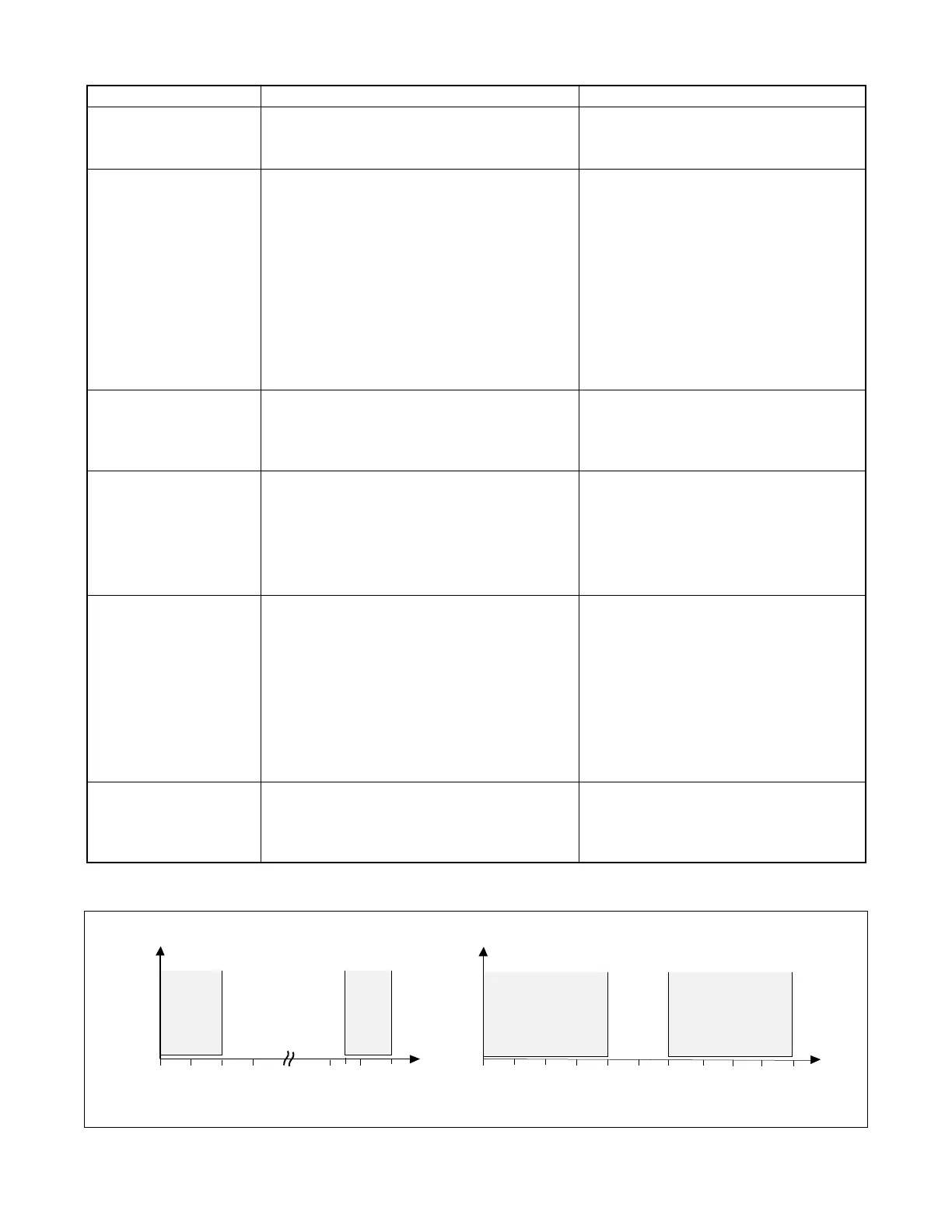
Figure 14: Adjustable Switching Range
Troubleshooting Logix 500 Digital Positioners
Factory setting of the limit switches LS1 and LS2: 0% – 3% from the end position
0 10 20 30 80 90 100%
0 10 20 30 40 50 60 70 80 90 100%
85
0
Rotary Version
LS1
LS2
LS1
LS2
Switch output
Switch output
Linear Version
Stroke
Rotary angle
 Loading...


