User instructions - Digital Positioner 3200MD LGENIM0059-01 10/08
24
5. Remove the five wire connections from the main PCB assembly
(six wire connections if the unit is equipped with the 4-20 mA
analog output option).
6. Remove the retaining screw from the main PCB assembly and
lift the main PCB out of the housing.
7. Remove the four screws from the regulator base. Verify that as
regulator is removed, the O-ring and filter remain in the counter-
bore (please see Figure 11).
8. Remove tubing and barbed fitting from the regulator base.
9. Install barbed fitting and tubing to the new regulator.
10. Verify O-ring and filter are in the counterbore. Install new regula-
tor using 8-32 x ½" screws.
NOTE: Do not mix the regulator with those from older Logix po-
sitioners. Older models contain regulators with different settings
that will not work in the Logix 3200MD model. The regulator
pressure setting is printed on the top of the regulator. The Logix
3200MD regulator is set to 17.4 psig.
11. Install the main PCB into the housing. Insert the retaining screw
through the board into the threaded boss and tighten evenly,
using a Phillips screwdriver. Do not overtighten.
12. Reinstall the five wire connections (six wire connections if the
unit is equipped with the 4-20 mA analog output option).
13. Install the plastic board cover. Insert the three retaining screws
through the plastic cover into the threaded boss and tighten
evenly, using a Phillips screwdriver. Do not overtighten (see
Figure 15).
14. Reinstall all covers.
8.3 Checking or Setting Internal
Regulator Pressure
To check or set the internal regulator pressure, refer to Figure 16
and proceed as outlined below. The tools and equipment used in the
next procedure are from indicated vendors. The following tools are
required:
• Calibratedpressuregauge(0to30psi)
•
1
⁄16" flexible tubing
• BarbedTee(ClippardMinimaticpartnumberT22-2orequivalent)
•
3
⁄32" Allen wrench
•
3
⁄8" open-end wrench
c
WARNING: Observe precautions for handling electrostati-
cally sensitive devices.
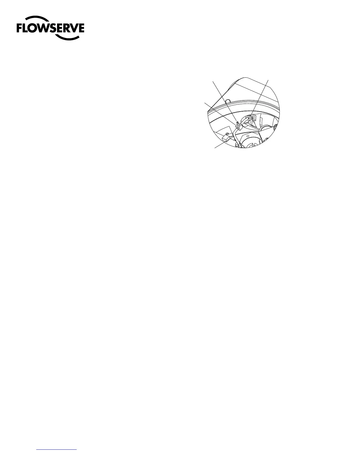
Figure 16: Driver Module Regulator Pressure Check
3FHVMBUPS1SFTTVSF
5FTU1PSU
#BSCFE5FF
$MJQQBSE.JOJNBUJD
1BSU/P5
'MFYJCMF5VCF
GSPN3FHVMBUPS
%SJWFS.PEVMF
#BSCFE'JUUJOH
Y
c
1. Make sure the valve is bypassed or in a safe condition.
2. Remove the main cover.
3. Remove the plastic board cover by removing the three retaining
screws.
4. Remove the
1
⁄16" flexible tubing from the barbed fitting on the
side of the driver module.
5. Obtain a barbed tee and two pieces of
1
⁄16" flexible tubing, a few
inches in length each.
6. Position the barbed tee between the internal regulator and the
driver module by connecting the
1
⁄16" flexible tubing, found in
the positioner, to one side of the barbed tee. Using one of the
new flexible tubing pieces, connect the barbed tee to the barbed
fitting on the side of the driver module. Connect the remaining
port on the barbed tee to a 0 to 30 psi pressure gauge.
7. Reconnect the air supply to the positioner and read the internal
regulator pressure on the 0 to 30 psig gauge. The internal
pressure should be set to 17.4 ±0.2 psig. If adjustment is needed,
loosen the set screw retaining nut on the top of the regulator us-
ing the
3
⁄8" open-end wrench. Then adjust the regulator pressure
by turning the set screw on the top of the regulator with the
3
⁄32"
Allen wrench.
8. Once the regulator pressure is set, tighten the set screw retain-
ing nut on the top of the regulator, remove the air supply to the
positioner, remove the barbed tee, and reconnect the flexible
tubing from the regulator to the barbed fitting on the side of the
driver module.
9. Install the plastic board cover. Insert the three retaining screws
through the plastic cover into the threaded boss and tighten
evenly, using a Phillips screwdriver. Do not overtighten (see
Figure 15).
10. Reinstall all covers.