User instructions - Digital Positioner 3200MD LGENIM0059-01 10/08
31
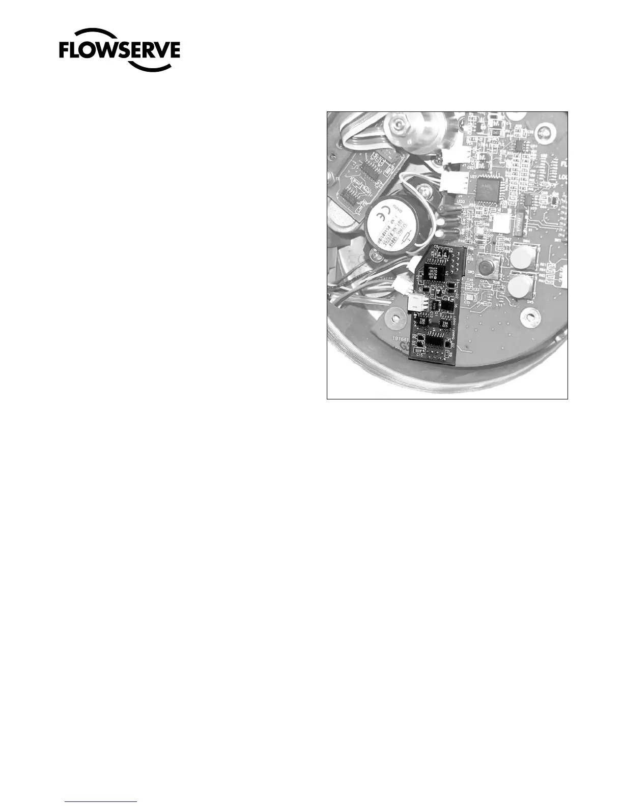
7. Align the two connectors on the new 4-20 mA analog output
board with the mating sockets on the main PCB board and
gently press the connectors together.
8. Connect the two wire connection coming from the User Inter-
face board to the side of the 4-20 mA analog output board.
9. Install the plastic board cover. Insert the three retaining screws
through the plastic cover into the threaded boss and tighten
evenly, using a Phillips screwdriver. Do not overtighten.
10. Connect the Analog Output filed termination wiring to the
Analog Output terminals on the User Interface board (see Figure
23.)
11. Reinstall all covers.
Figure 24: 4-20 mA Analog Output Board