63
Logix
®
520MD+ and 510+ Digital Positioners FCD LGENIM0105-15-AQ – 05/16
flowserve.com
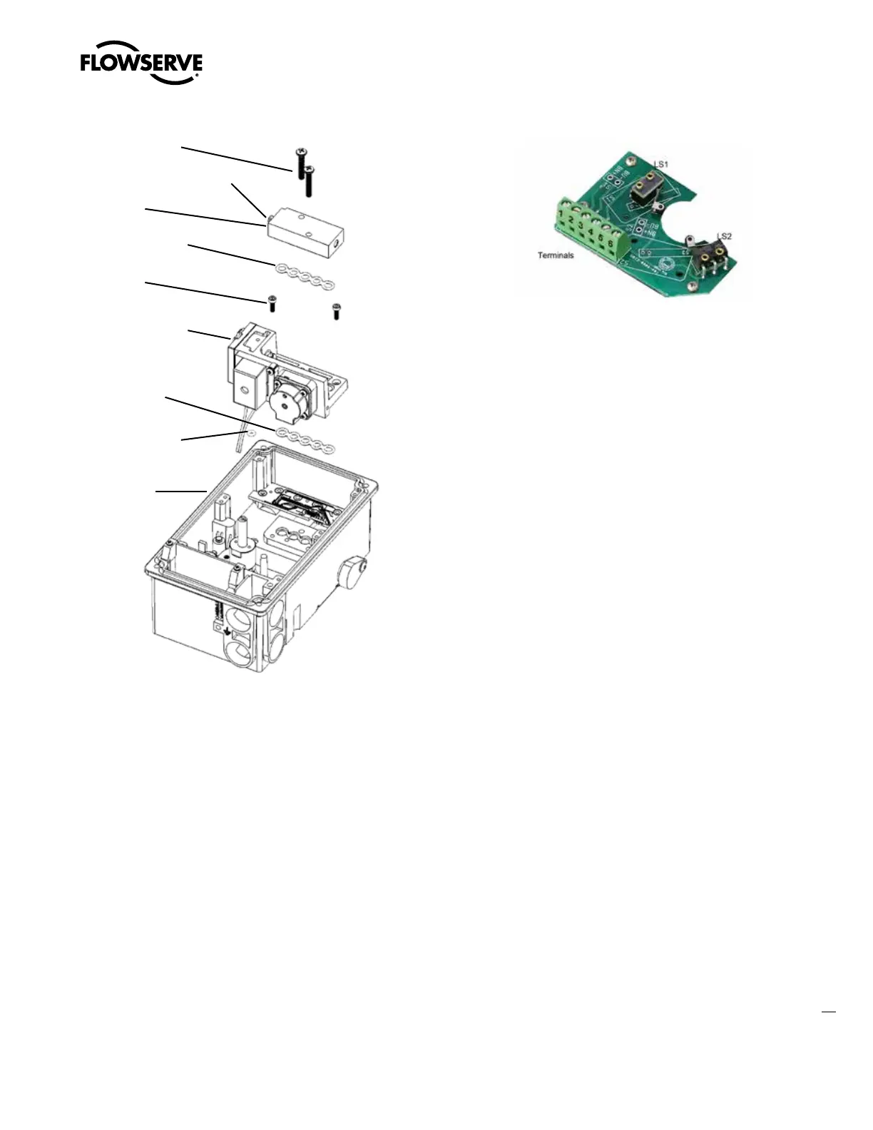
18.10 Replacing a Single Acting Pilot Relay
Refer to Figure 57.
Removal
1. Remove the Main Board. See procedure above.
2. Remove the two relay assembly screws.
3. Remove the single acting relay.
4. Remove the supply plug screw and O-ring.
5. Remove the Manifold gasket.
Installation
1. Place the Manifold gasket.
2. Place the supply plug O-ring and screw.
3. Place the single acting relay.
4. Place the two relay assembly screws.
5. Reassemble the main board and covers and calibrate.
Figure 55: Double Acting Relay Assembly
Spool Block
Screws (2)
Base
Manifold
O-Ring
Double Acting
Relay Manifold
Assembly
Manifold
Screws (2)
Manifold
Gasket (2 of 2)
Manifold
Gasket (1 of 2)
Spool & Clip
Spring
Spool/Block
Assembly
Figure 56: Clip Spring Orientation