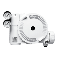
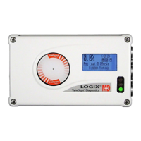
Do you have a question about the Flowserve APEX 7000 and is the answer not in the manual?
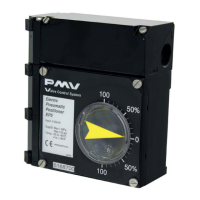
Overview of the P4 pneumatic valve positioner, its features, and applications.
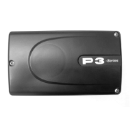
Details on the P5 pneumatic positioner base unit and its modular design.
Features and benefits of the EP5 positioner, highlighting modularity for various applications.
Instructions for using storage seals on P5/EP5 enclosure entry points.
Specifies the necessary quality and pressure for the supply air.
Details on mounting the positioner to the actuator and spindle installation.
Procedure to adjust the indicator on P5/EP5 models.
Procedure to adjust the indicator on P4 models.
Steps for cleaning and inspecting the pilot valve assembly.
Procedure for installing and centering the diaphragm.
Instructions for accessing and installing the feedback spring.
Steps for removing and installing the balance arm.
Procedure for accessing, cleaning, and installing the lower arm.
Guidance on O-ring maintenance and selection of grease.
Instructions for replacing the filter plug and checking for moisture.
Detailed listing of spare parts for the P4 positioner.
Exploded view illustrating spare parts for P5/EP5 positioners.
Detailed listing of spare parts for P5/EP5 positioners.
Specific spare parts for the I/P unit used with P5/EP5.
Step-by-step guide for calibrating the APEX 7000 positioner.
| Type | Digital Valve Positioner |
|---|---|
| Operating Temperature | -40 to 185 °F (-40 to 85 °C) |
| Enclosure | NEMA 4X, IP66 |
| Materials | Aluminum, Stainless Steel |
| Communication Protocol | HART |
| Supply Pressure | 20 to 100 psi |
| Input Signal | 4-20 mA |
| Mounting | IEC 534-6 (NAMUR) |

