EP5 Electro Pneumatic Digital Positioner FCD PMENIM0006-00-A5 12/18
12
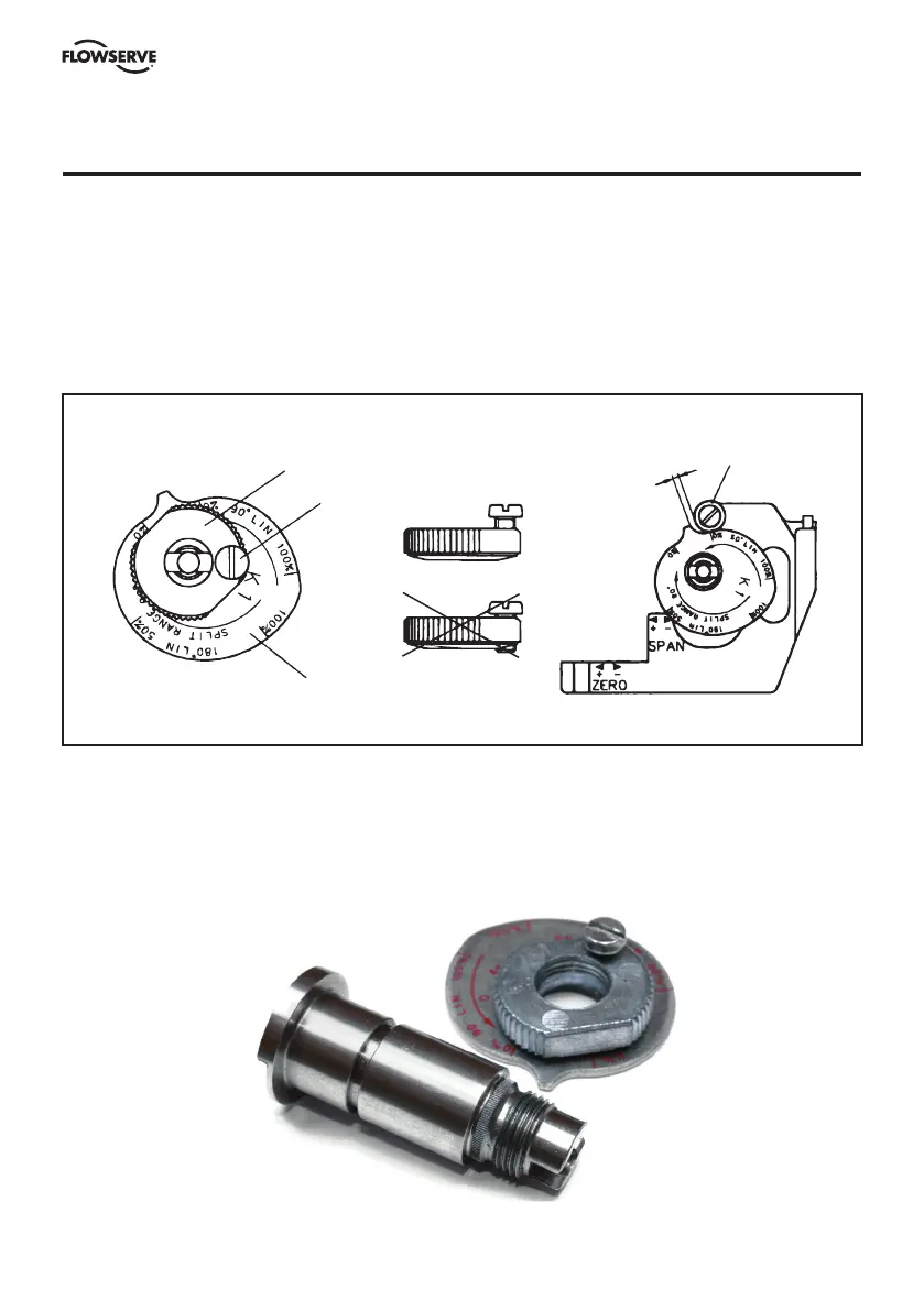
6. Cam adjustment
With the cover and indicator removed, loosen the screw 1 and turn the cam locking nut 2
counterclockwise until the cam loosens. Adjust the cam 3 as desired making sure that the ball
bearing 4 always is riding on an active lobe on the cam. To secure the cam, make sure that screw 1
is backed out from the locking nut 2 then finger tighten the locking nut and tighten screw 1. Install
and adjust the indicator and reinstall cover.
3
1
2
4
1-2 mm (1/16")
Correct
Incorrect
Splined cam
As an option it is possible to configure the P5 with a splined cam. This design improves how
the cam is engaged to the shaft and will improve performance. The splined cam will generate an
increased safety in critical applications. See order code for more information how to order.