EP5 Electro Pneumatic Digital Positioner FCD PMENIM0006-00-A5 12/18
15
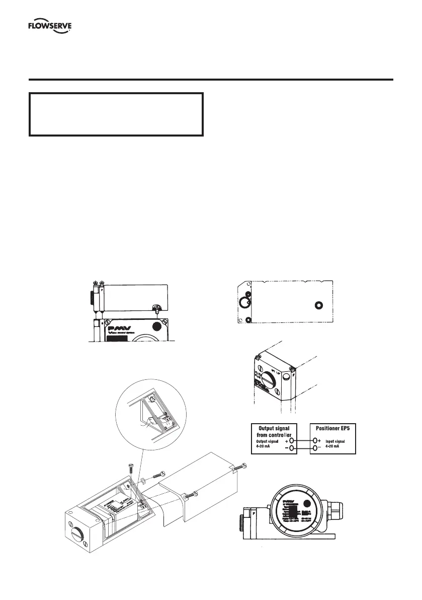
The I/P unit is mounted directly on top of the
positioner unit.
No external air supply is needed since the I/P
unit is supplied with air from the positioner
unit.
Port I on the positioner unit will be plugged
when the I/P unit and the appropriate gauge
block gasket installed. The I/P unit accepts a
4-20 mA input signal.
The I/P unit is equipped with a built in 30
micron filter (Fig 4).
Caution: Do not operate the unit without filter
and filterplug installed.
Ensure that wiring between I/P and terminals
are properly seated in rubber clamp.
Do not unscrew filterplug when the positioner is
pressurized.
Span and Zero for the I/P converter is factory
set and can not be adjusted
Fig 3
Fig 1
Fig 2
Fig 4
Fig 5
Fig 6
10. I/P Unit (EP5/APEX 7000)
WARNING!
Units installed in hazardous areas must
have proper approvals.
 Loading...


