EP5 Electro Pneumatic Digital Positioner FCD PMENIM0006-00-A5 12/18
22
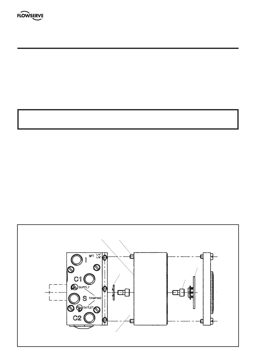
13. Feedback unit (P5 or EP5)
See feedback module instructions for connections and calibration.
The P5 or EP5, Valve Control System, can easily be equipped with a Feedback unit, model F5. This
unit will mount directly on top of the Pneumatic positioner replacing the positioner front cover. The
O-ring located on the bottom of the Feedback unit, F5, will provide the same sealing or draining
capabilities as the front cover. The indicator and front cover from the positioner unit can then be
installed on to the Feedback unit.
Installing the feedback unit.
– Remove the front cover, indicator, and Allen head screw from the top of the positioner spindle.
– Install the drive coupling 4 and adjust the O-ring seal on the bottom in either sealed or draining
position. (See section 6, page 10).
– Install the Feedback unit 9 on top of the Positioner unit, making sure the coupling is properly
engaged before tightening the four screws 5.
– Make electrical connections and tighten cable glands. (See F5 manual for details).
– Adjust cams and/or potentiometer to desired position.
– Install the indicator and front cover.
WARNING!
Units installed in hazardous locations must have proper approvals.
9
5
4
3
2
O-ring seal
 Loading...


