EP5 Electro Pneumatic Digital Positioner FCD PMENIM0006-00-A5 12/18
20
Lower arm
Once the front cover is removed, the lower arm can be easily accessed.
Remove the indicator, feedback spring and the cam.
Loosen screw 2 and remove twist stop 1.
Remove screw 3, lower arm 4, rod 5 and spring 6.
Check rod and lower arm for wear, replace if necessary. Clean the rod and install it in the lower arm.
The lower arm should move easily and smoothly.
Install the lower arm and rod assembly into the positioner housing, making sure that the spring 6 is
attached properly to the lower arm and positioner housing.
Secure the lower arm and rod assembly with the screw 3.
Check again that the lower arm moves smoothly.
Apply a small amount of grease on the small tongue on the lower arm, then install and secure the
twist stop.
Install cam, feedback spring, indicator and front cover.
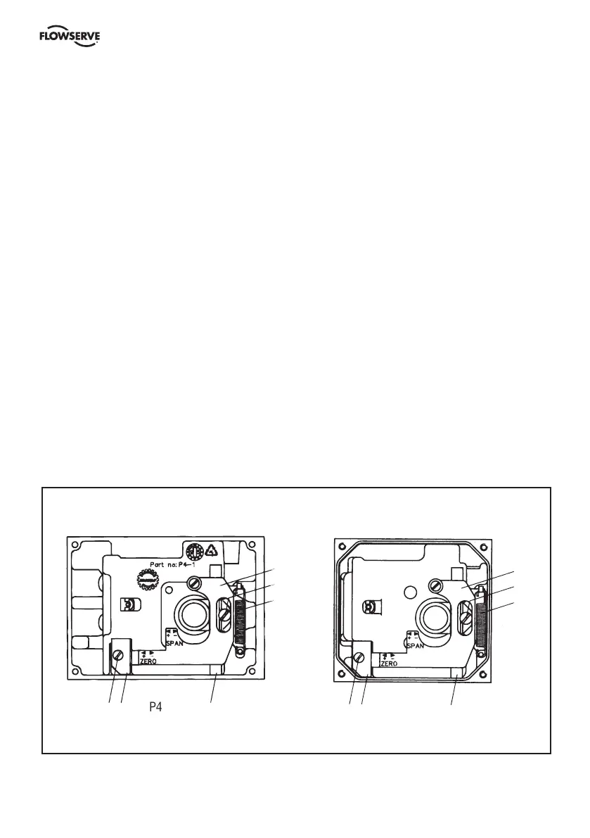
P4
6
2
4
3
4
3
2
6
5
1
1
P5/EP5